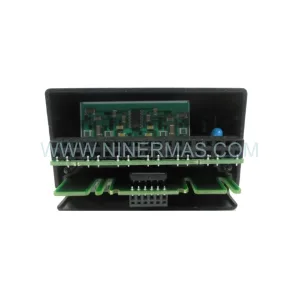
Original Industrial Spare Part
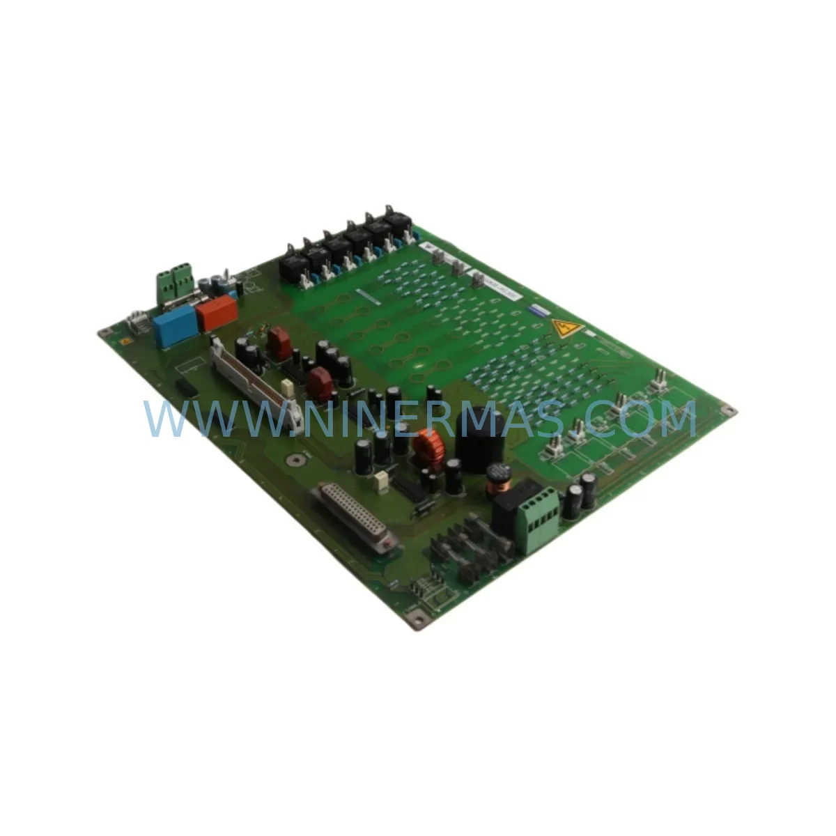
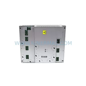
Siemens 6SE7041-3FK85-1JA0 Retrofit-Compatible AC Drive
Verify the part, confirm the platform family, and move straight into quotation with the right commercial details.
RFQ Ready
- SKU6SE7041-3FK85-1JA0
- CategoryPLC & Industrial Automation Modules
- BrandSiemens
- SupportAvailability, lead time, condition, and shipping coordination
How Buyers Usually Use This Page
- Confirm the exact part number and platform family before sending the quote request.
- Use direct email when quantity, condition, and destination are already defined internally.
- Switch to the broader brand or category archive when you need alternates nearby.
Series Navigation
Move through the most common platform families behind this part.
Product RFQ
Send this part directly for quotation.
Include quantity, required condition, destination country, and target delivery timing. Current reference: Siemens 6SE7041-3FK85-1JA0 Retrofit-Compatible AC Drive with SKU 6SE7041-3FK85-1JA0.
Siemens 6SE7041-3FK85-1JA0 Retrofit-Compatible AC Drive: Legacy System Compatibility & Smooth Upgrade Path
The Siemens 6SE7041-3FK85-1JA0 is a high-power AC variable frequency drive from the SIMOVERT MASTERDRIVES series, engineered for demanding industrial applications in processing, petrochemical, power generation, and heavy manufacturing environments. As legacy SIMOVERT MASTERDRIVES installations approach end-of-service milestones, plant engineers and maintenance teams increasingly require retrofit-compatible replacement units that can be integrated without full system redesign. This unit is stocked and pre-tested to serve exactly that purpose — enabling controlled, low-risk modernization of aging drive infrastructure while preserving existing control architecture and minimizing unplanned downtime.
The 6SE7041-3FK85-1JA0 operates within the SIMOVERT MASTERDRIVES Vector Control platform, supporting high-dynamic torque control for synchronous and asynchronous motors. Its compact power section and modular design make it a preferred choice for retrofit projects where cabinet space is constrained and rewiring must be minimized. Whether you are replacing a failed unit on an emergency basis or executing a planned lifecycle upgrade across a multi-drive control cabinet, this model provides the electrical and mechanical compatibility required for a direct swap with minimal engineering intervention.
Upgrade Compatibility Table
| Parameter | Details |
|---|---|
| SKU / Part Number | 6SE7041-3FK85-1JA0 |
| Series | SIMOVERT MASTERDRIVES Vector Control |
| Drive Type | AC Variable Frequency Drive (VFD) |
| Mounting / Installation | Cabinet-mount; compatible with standard SIMOVERT MASTERDRIVES chassis frames |
| Communication Interfaces | PROFIBUS-DP via CBP2 option board; USS protocol via serial interface |
| Replacement Compatibility | Direct retrofit for same-frame SIMOVERT MASTERDRIVES units; verify firmware revision and option board configuration before swap |
| Terminal / Wiring Compatibility | Standard SIMOVERT power and control terminal layout; confirm PE, DC bus, and motor output terminal assignments against existing drawings |
| Backplane / Rack Interface | Standalone cabinet-mount; no backplane dependency |
| Commissioning Tool | STARTER / DriveMonitor via USS or PROFIBUS; parameter set upload/download recommended before swap |
| Key Commissioning Steps | Parameter backup, motor data re-entry, encoder feedback verification, ramp time confirmation, I/O function block check |
| Pre-Shipment Testing | Full power-on functional test performed prior to dispatch |
| Warranty | 12 months from date of shipment |
| Origin | Germany |
| Stock Status | Available — contact for lead time confirmation |
Retrofit Planning for Existing Automation Systems
Replacing a SIMOVERT MASTERDRIVES unit in an active production environment requires careful pre-engineering to avoid configuration mismatches and extended downtime. Before the 6SE7041-3FK85-1JA0 is installed, the retrofit team should conduct a full audit of the existing drive cabinet, including the power supply module (PSM), the inverter unit, and any installed option boards such as the CBP2 PROFIBUS communication board or the SBP encoder evaluation board. These option boards carry drive-specific parameter assignments and must be either transferred to the replacement unit or reconfigured from a saved parameter file.
In multi-drive installations, the DC bus link between the SIMOVERT MASTERDRIVES Rectifier/Regenerative Unit and the inverter section must be de-energized and verified safe before any mechanical work begins. The DC bus capacitors in high-power MASTERDRIVES units retain charge for several minutes after power-off; always follow the discharge wait time specified in the unit’s safety documentation. Once the old unit is removed, inspect the cabinet for thermal damage, contaminated cooling air paths, and worn cable insulation — conditions that frequently accompany drive failures in long-running installations.
Terminal wiring for the 6SE7041-3FK85-1JA0 follows the standard SIMOVERT MASTERDRIVES layout. The U2, V2, W2 motor output terminals, the PE ground connection, and the DC bus P and N terminals should be reconnected according to the original as-built drawings. If the original drawings are unavailable, the motor cable routing and terminal markings on the existing unit should be photographed before removal. Control wiring to the CU (Control Unit) — including analog speed reference inputs, digital enable signals, fault relay outputs, and the 24 VDC auxiliary supply — must be reconnected with polarity and shielding intact.
For systems using PROFIBUS-DP as the primary communication link to a SIMATIC S7-300 or SIMATIC S7-400 PLC, the drive’s PROFIBUS node address must be set to match the original unit before the network is re-enabled. Address mismatches will cause the PLC to report a station failure and may trigger a controlled shutdown of dependent process loops. If the plant uses a SIMATIC HMI OP/TP panel for local drive monitoring, verify that the HMI tag addresses referencing drive parameters (speed setpoint, actual current, fault code) remain valid after the swap — parameter mapping differences between firmware versions can cause display errors that are easily overlooked during initial commissioning.
In applications where the drive controls a motor coupled to a high-inertia load — such as a centrifugal compressor, a large pump, or a conveyor — the ramp-up and ramp-down times stored in the original parameter set are critical. These values are tuned to the specific load inertia and must be restored exactly. If the parameter file was not backed up prior to the original drive failure, the commissioning engineer will need to re-tune the ramp times during a controlled test run, ideally under reduced load conditions. A SIMOVERT MASTERDRIVES programming cable (USS interface) or a PROFIBUS-connected laptop running STARTER commissioning software is required for this process.
Where the existing installation includes a SIMOVERT MASTERDRIVES Braking Module and external braking resistor, confirm that the braking chopper threshold and resistor thermal model parameters are correctly set in the replacement unit. Incorrect braking configuration is a common source of overvoltage trips during deceleration, particularly in regenerative load applications. Additionally, if the system uses a line filter or output dU/dt filter in series with the drive, these components should be inspected for condition and continuity as part of the retrofit process — a degraded filter can cause EMC non-compliance or motor insulation stress even after the drive itself has been successfully replaced.
Downtime Control During System Migration
Minimizing production downtime during a SIMOVERT MASTERDRIVES replacement requires a structured pre-outage preparation process. The most effective approach is to complete all parameter backup, spare parts staging, and wiring documentation review before the maintenance window begins. Using DriveMonitor or STARTER, upload the complete parameter set from the existing drive to a laptop while the drive is still operational — this single step eliminates the most time-consuming part of post-swap commissioning and protects the original control logic from being lost.
During the outage, work sequentially: isolate and lock out the incoming supply, verify DC bus discharge, remove the failed unit, install the 6SE7041-3FK85-1JA0, reconnect power and control terminals, restore option boards, download the saved parameter set, and perform a no-load test run before reconnecting the motor. This sequence, when followed with a pre-prepared checklist, typically allows a competent drive engineer to complete the physical swap and initial commissioning within a single shift.
For critical process lines where even a single-shift outage is unacceptable, consider staging the replacement unit in a parallel test cabinet with a matched motor for pre-commissioning and parameter verification before the production outage. This approach — sometimes called a “hot swap preparation” — allows the production window to be reduced to the time required for physical installation and final I/O verification only. It also provides an opportunity to confirm that the replacement unit’s firmware version is compatible with the existing option boards and communication configuration before the unit enters service.
Throughout the migration, maintain continuity of the safety interlock chain. The drive’s fault relay output, which is typically wired into the plant’s emergency stop or process interlock circuit, must be verified functional before the drive is released for production. A missed fault relay connection is a safety risk and a common cause of post-commissioning incidents in drive retrofit projects. Document all changes made during the retrofit — including any parameter adjustments, wiring modifications, and firmware version details — and update the as-built drawings accordingly to support future maintenance activities.
Retrofit Support FAQ
Q1: Is the 6SE7041-3FK85-1JA0 a direct drop-in replacement for my existing SIMOVERT MASTERDRIVES unit?
In most cases, yes — provided the replacement unit is the same frame size and power rating as the original. You should verify the option board configuration (PROFIBUS, encoder, I/O expansion) and firmware revision before installation. If your existing unit carries a non-standard option board combination, contact us before ordering to confirm compatibility.
Q2: What commissioning steps are required after installing the replacement drive?
At minimum: restore the parameter set from backup (or re-enter motor nameplate data and application parameters manually), verify PROFIBUS node address, confirm analog and digital I/O assignments, check encoder feedback signal integrity if applicable, and perform a no-load test run followed by a loaded test run at reduced speed. Full commissioning documentation is available upon request.
Q3: Has this unit been tested before shipment?
Yes. Every unit undergoes a full power-on functional test prior to dispatch. Test records are available upon request. Units are packed in anti-static protective packaging with mechanical protection suitable for international freight.
Q4: What warranty and after-sales support is provided?
All units supplied by NINERMAS carry a 12-month warranty from the date of shipment, covering manufacturing defects and functional failures under normal operating conditions. In-stock units are available for rapid dispatch to minimize your production downtime. For urgent requirements, contact our technical sales team directly to confirm availability and lead time.
| Product Series | SIMOVERT |
|---|---|
| Country of Origin | DE |
Catalog Continuation
More Siemens modules in the catalog.
Use the brand lane to compare nearby part numbers, platform-adjacent modules, and other inquiry-ready listings before sending your final RFQ.
SKU: 6ES7410-5HX08-0AB0
Siemens 6ES7410-5HX08-0AB0 Retrofit-Compatible CPU for Legacy Systems
SKU: 6SL3060-4AB20-0AA0
SIEMENS 6SL3060-4AB20-0AA0 Service-Ready Spare Part for Industrial Maintenance
SKU: 6SE7038-6WK84-1BH0
Siemens 6SE7038-6WK84-1BH0 Retrofit-Compatible AC Drive
Catalog Continuation
Alternative parts within PLC & Industrial Automation Modules.
Stay inside the same system family when you need substitutes, adjacent modules, or a broader shortlist for procurement review.
SKU: 3AUA0000058712/ZDPI-01
ABB 3AUA0000058712/ZDPI-01 Retrofit-Compatible Adapter Board
SKU: DSQC431 3HAC036260-001
ABB DSQC431 3HAC036260-001 Retrofit LVMC MDU Legacy Systems