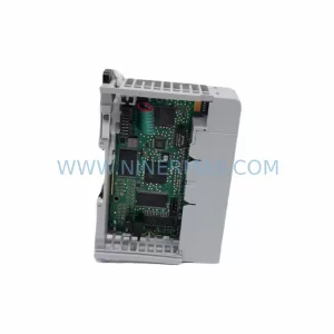
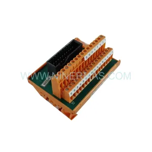
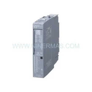
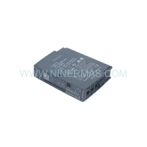
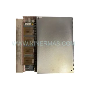
Original Industrial Spare Part
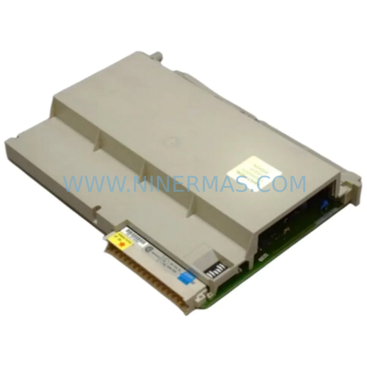
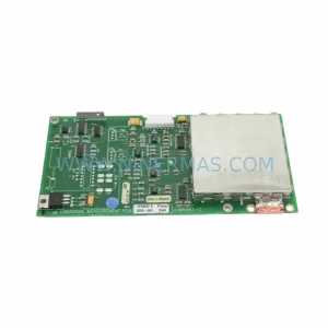
SIEMENS 6ES5454-4UA13 Retrofit-Compatible Digital Output
Verify the part, confirm the platform family, and move straight into quotation with the right commercial details.
RFQ Ready
- SKU6ES5454-4UA13
- CategoryPLC & Industrial Automation Modules
- BrandSiemens
- SupportAvailability, lead time, condition, and shipping coordination
How Buyers Usually Use This Page
- Confirm the exact part number and platform family before sending the quote request.
- Use direct email when quantity, condition, and destination are already defined internally.
- Switch to the broader brand or category archive when you need alternates nearby.
Series Navigation
Move through the most common platform families behind this part.
Product RFQ
Send this part directly for quotation.
Include quantity, required condition, destination country, and target delivery timing. Current reference: SIEMENS 6ES5454-4UA13 Retrofit-Compatible Digital Output with SKU 6ES5454-4UA13.
SIEMENS 6ES5454-4UA13 Retrofit-Compatible Digital Output for Legacy Systems
The SIEMENS 6ES5454-4UA13 is a 32-channel digital output module originally designed for the SIMATIC S5 programmable controller family. As production lines age and original equipment manufacturers discontinue support for legacy platforms, the 6ES5454-4UA13 has become one of the most sought-after retrofit and replacement components in industrial automation. Whether you are maintaining an existing S5-115U, S5-135U, or S5-155U installation, or executing a controlled migration toward a modern control architecture, this module provides the output capacity and signal compatibility required to keep your plant running without a full system overhaul.
NINERMAS stocks the 6ES5454-4UA13 as a tested, verified unit backed by a 12-month warranty. Every unit undergoes functional output verification, backplane connector inspection, and load simulation testing before shipment. Inventory is maintained to support urgent breakdown replacements as well as planned retrofit projects with longer lead times.
Upgrade Compatibility Table
| Parameter | 6ES5454-4UA13 (This Unit) | Retrofit / Migration Notes |
|---|---|---|
| Output Channels | 32 × DC digital outputs | Verify field wiring terminal count before swap |
| Output Voltage | 24 V DC | Confirm cabinet power supply (e.g. 6ES5955-3LC41) output rating |
| Backplane Interface | S5 sub-rack bus connector | Compatible with UR1, UR2, EG183U, EG186U expansion racks |
| Module Address | Set via DIP switch on module face | Match address to existing CPU program; document before removal |
| Communication Protocol | S5 parallel backplane bus | Not directly compatible with PROFIBUS or PROFINET without gateway |
| Installation Space | Single slot, standard S5 sub-rack | Confirm slot availability; no additional mounting hardware required |
| Replacement Compatibility | Direct drop-in for 6ES5454-4UA12, 6ES5454-4UA11 | Verify firmware revision of CPU (e.g. 6ES5948-3UA21) for output map |
| Commissioning Requirement | Address switch setting + output force test | Use STEP 5 programmer or PG 740 / PG 760 for diagnostics |
| Warranty | 12 months from shipment date — covers functional failure under normal operating conditions | |
Retrofit Planning for Existing Automation Systems
A successful retrofit using the 6ES5454-4UA13 begins well before the module arrives on site. Engineers responsible for the upgrade should start by auditing the existing S5 sub-rack configuration. In a typical S5-135U or S5-155U cabinet, the central rack may house a 6ES5948-3UA21 CPU alongside power supply modules such as the 6ES5955-3LC41, which feeds 24 V DC to the output modules. Confirming that the power supply has sufficient current headroom for 32 active output channels is a critical pre-installation step that is frequently overlooked during emergency breakdown replacements.
Terminal wiring is the next area of focus. The 6ES5454-4UA13 uses a front connector that mates with the module’s face terminals. Before removing the failed unit, photograph or document every wire position on the existing front connector. In many legacy installations, wire labels have faded or been removed during previous maintenance cycles. A wiring audit at this stage prevents mis-termination errors that can damage field devices or cause unsafe output states during commissioning.
For plants that are simultaneously upgrading their communication infrastructure, the 6ES5454-4UA13 can coexist with PROFIBUS DP networks when a 6ES5318-8MA12 IM interface module is used to bridge expansion racks to the central CPU. This allows engineers to add modern distributed I/O — such as ET 200 remote stations — to the same control system without replacing the existing S5 digital output infrastructure. In cases where the migration roadmap calls for an eventual move to SIMATIC S7-300 or S7-400, the output module can remain in service during the transition period, reducing the scope and cost of the initial upgrade phase.
HMI screens connected to the existing system via 6ES5734-1BD20 serial communication processors or similar CP modules typically do not require reprogramming when a like-for-like output module replacement is performed. However, if the module address is changed during the swap — for example, because the original slot is physically damaged — the CPU program’s output assignment table must be updated in STEP 5, and any HMI tag references tied to that output byte must be revised accordingly.
I/O expansion using 6ES5700-series expansion units connected via the S5 bus is fully supported alongside the 6ES5454-4UA13. Engineers planning to add input capacity during the same maintenance window should consider installing a 6ES5431-4UA12 digital input module in an adjacent slot to consolidate the upgrade scope and minimize future downtime events. Signal isolators — particularly for long cable runs to field devices — should be verified for compatibility with the 24 V DC output signal level of the 6ES5454-4UA13 before the system is returned to automatic operation.
Programming cables such as the 6ES5734-1BD20 or a USB-to-TTY adapter compatible with STEP 5 software are required for any address change verification or program modification during commissioning. Ensure the programming device is available on site before the maintenance window begins to avoid delays caused by missing tooling.
Downtime Control During System Migration
Minimizing production downtime during a digital output module replacement requires a structured approach to pre-staging, execution, and verification. The 6ES5454-4UA13 is a hot-swap-capable module in terms of physical installation, but the CPU must be placed in STOP mode before the module is removed to prevent uncontrolled output states that could activate field actuators, solenoids, or motor starters connected to the output channels.
Before entering STOP mode, capture a complete memory backup of the CPU program using a STEP 5 programming device. Store the backup on both the programming device and an external medium. This protects the control logic in the event that a power interruption during the swap causes a CPU memory fault. In installations where the CPU uses a 6ES5375-1LA15 memory submodule, verify that the submodule is seated correctly after the replacement is complete, as vibration during module removal can occasionally dislodge adjacent components.
Once the 6ES5454-4UA13 is installed and the front connector is re-attached, perform an output force test channel by channel using the STEP 5 force function before returning the CPU to RUN mode. This confirms that each output channel is driving its corresponding field device correctly and that no wiring errors were introduced during the swap. Document the test results as part of the maintenance record for the installation.
For plants operating continuous processes where even brief STOP mode periods are unacceptable, a parallel output strategy using a temporary relay interface panel can maintain field device control while the module is exchanged. This approach adds complexity but is appropriate for critical applications such as chemical dosing, conveyor sequencing, or safety-rated interlock circuits. NINERMAS can advise on pre-tested relay interface solutions for such scenarios upon request.
Total replacement time for a prepared team with documentation and tooling in hand is typically 30 to 90 minutes, including the output force test. Planning the maintenance window around this estimate, with a buffer for unexpected wiring discrepancies, gives operations teams a realistic expectation for production recovery time.
Retrofit Support FAQ
Q1: Is the 6ES5454-4UA13 a direct replacement for the 6ES5454-4UA12?
Yes. The 6ES5454-4UA13 is the later hardware revision of the same module family and is a direct drop-in replacement for the 6ES5454-4UA12 and 6ES5454-4UA11. No program changes are required provided the module is installed in the same slot with the same DIP switch address settings. Verify the front connector wiring matches the original before powering up.
Q2: Does NINERMAS test the module before shipment?
Yes. Every 6ES5454-4UA13 unit is functionally tested prior to dispatch. Testing includes backplane connector verification, output channel activation under load, and visual inspection of the PCB and front connector interface. A test report is available upon request. All units are covered by a 12-month warranty from the date of shipment.
Q3: What commissioning steps are required after installation?
After physical installation, set the DIP switches on the module face to match the address used in the original configuration. Connect the front connector and verify all field wiring terminations. Place the CPU in RUN mode and use the STEP 5 force function to test each output channel individually. Confirm that field devices respond correctly before releasing the system to automatic operation. A programming device compatible with STEP 5 is required for this process.
Q4: Can this module be used in an S5-115U system?
Yes, the 6ES5454-4UA13 is compatible with the S5-115U, S5-135U, and S5-155U central racks as well as their associated expansion units. Confirm the sub-rack slot type and bus connector alignment before installation. For S5-115U installations with compact racks, verify the physical slot depth is sufficient for the module’s backplane connector.
| Product Series | SIMATIC S5 |
|---|---|
| Country of Origin | DE |
Catalog Continuation
More Siemens modules in the catalog.
Use the brand lane to compare nearby part numbers, platform-adjacent modules, and other inquiry-ready listings before sending your final RFQ.
SKU: 6ES7234-4HE32-0XB0
Siemens 6ES7234-4HE32-0XB0 Service-Ready Spare Part
SKU: 6DD1606-0AD1 A5E00496009
Siemens 6DD1606-0AD1 Safety-Reliable Drive CPU for Critical Control
SKU: NCU572.2 6FC5357-0BB21-0AE0
Siemens 6FC5357-0BB21-0AE0 Retrofit NCU for Legacy Systems
Catalog Continuation
Alternative parts within PLC & Industrial Automation Modules.
Stay inside the same system family when you need substitutes, adjacent modules, or a broader shortlist for procurement review.
SKU: 16-167627-00 8122 410 05002, 4022.470.78191 8122 410 55702 16-273491-00
Novellus 16-167627-00 Service-Ready Industrial Spare Part
SKU: 2305451-C DT2000 0626 P2, OLE36-10632-02
Advanced Energy 2305451-C Service-Ready Industrial Spare Part