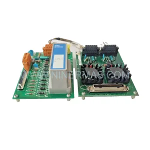
Original Industrial Spare Part
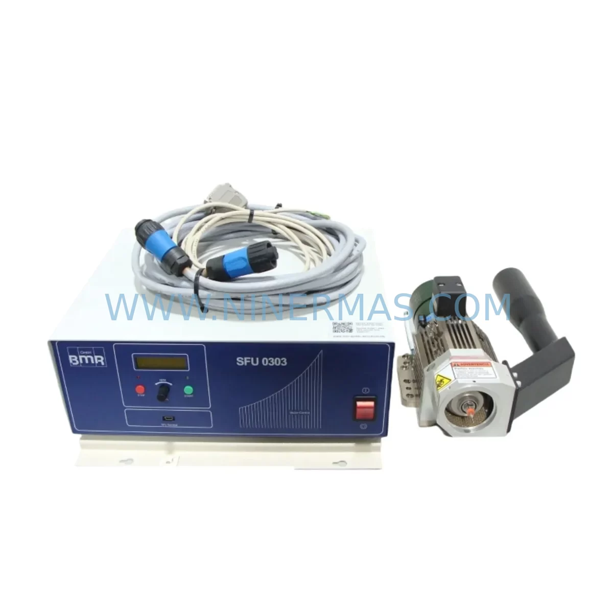
SEL SEL-547 05470X155XXX2XX Retrofit-Compatible Protection Relay
Verify the part, confirm the platform family, and move straight into quotation with the right commercial details.
RFQ Ready
- SKUSEL-547 05470X155XXX2XX
- CategorySIS Safety & Redundancy Systems
- BrandSEL
- SupportAvailability, lead time, condition, and shipping coordination
How Buyers Usually Use This Page
- Confirm the exact part number and platform family before sending the quote request.
- Use direct email when quantity, condition, and destination are already defined internally.
- Switch to the broader brand or category archive when you need alternates nearby.
Series Navigation
Move through the most common platform families behind this part.
Product RFQ
Send this part directly for quotation.
Include quantity, required condition, destination country, and target delivery timing. Current reference: SEL SEL-547 05470X155XXX2XX Retrofit-Compatible Protection Relay with SKU SEL-547 05470X155XXX2XX.
SEL SEL-547 05470X155XXX2XX Retrofit-Compatible Protection Relay for Legacy Systems
The SEL SEL-547 (part number 05470X155XXX2XX) is a high-reliability protection relay engineered for industrial power systems requiring precise overcurrent, voltage, and frequency protection. As legacy SEL-300 and SEL-400 series platforms reach end-of-life, the SEL-547 has become a critical retrofit component for engineers tasked with modernizing aging protection schemes without full substation redesign. NINERMAS maintains verified in-stock inventory of the SEL-547 05470X155XXX2XX, backed by a 12-month warranty and pre-shipment functional testing.
Upgrade Compatibility Table
| Parameter | Details |
|---|---|
| Part Number | SEL-547 / 05470X155XXX2XX |
| Manufacturer | Schweitzer Engineering Laboratories (SEL) |
| Function | Protection Relay — Overcurrent, Voltage & Frequency Protection |
| Communication Interface | EIA-232 / EIA-485 Serial; optional DNP3, MIRRORED BITS® |
| Mounting / Form Factor | Standard 19″ rack or panel-mount; compatible with SEL rack systems |
| Power Supply Input | 24–250 V DC / 120–240 V AC (verify nameplate before installation) |
| Replaces / Compatible With | SEL-547 legacy variants; cross-reference SEL-300G, SEL-351 protection schemes |
| Installation Requirement | Confirm terminal block wiring map, CT/PT ratios, and relay address settings |
| Communication Compatibility | DNP3 Level 2, SEL Fast Message, MIRRORED BITS® protocol |
| Retrofit Recommendation | Retain existing CT/PT wiring; re-map I/O terminals per SEL-547 instruction manual |
| Commissioning Focus | Verify protection settings file (*.RDB), test trip/close outputs, confirm SCADA polling |
| Warranty | 12 Months — Covers manufacturing defects; pre-shipment functional test included |
Retrofit Planning for Existing Automation Systems
Replacing an SEL-547 05470X155XXX2XX within an operating substation or industrial power panel demands careful pre-engineering. The relay typically resides in a protection and control (P&C) panel alongside companion devices such as the SEL-2505 Remote I/O Module, SEL-2030 Communications Processor, and SEL-300G Generator Protection Relay. Before removal of the legacy unit, engineers should document all existing wiring terminations on the rear terminal blocks, photograph the current settings file using SEL-5010 Software or AcSELerator Quickset, and confirm that the replacement 05470X155XXX2XX carries the same firmware baseline required by the site’s protection coordination study.
Power supply compatibility is the first checkpoint. The SEL-547 accepts a wide-range DC input, but field panels may supply 48 V DC, 110 V DC, or 125 V DC depending on the battery bank configuration. Confirm the station battery voltage before energizing the replacement module. Terminal block wiring on the SEL-547 follows a standard SEL rear-panel layout; however, older installations may use non-standard jumper configurations for CT shorting or PT fusing that must be replicated exactly on the new unit.
Communication link continuity is equally critical. Many legacy SEL installations use EIA-485 multidrop serial networks connecting the SEL-547 to an SEL-2030 Communications Processor or directly to a SCADA RTU. During the swap, the relay address (typically set via front-panel DIP switches or settings group) must match the address previously polled by the master station. If the site has migrated to IEC 61850 GOOSE messaging via an SEL-3530 Real-Time Automation Controller (RTAC), verify that the new SEL-547 firmware supports the required logical node mappings before cutover.
For installations where the SEL-547 interfaces with an SEL-651R Recloser Control or SEL-351 Overcurrent and Distance Relay in a coordinated protection scheme, the protection settings — including pickup levels, time-overcurrent curves, and reclosing sequences — must be re-entered and verified against the original coordination study. Use the AcSELerator Quickset SEL-5030 software to upload the archived settings file and perform a settings comparison before energizing. Where an SEL-2240 Axion modular I/O system or SEL-2505 Remote I/O is part of the control scheme, confirm that the MIRRORED BITS® channel assignments remain consistent after relay replacement.
Physical installation space should be confirmed before ordering. The SEL-547 occupies a standard 3U or 4U rack slot depending on the chassis variant; measure the available panel depth and confirm that the rear-terminal clearance meets SEL’s minimum bend radius requirements for CT wiring. Where space is constrained, a signal isolator or marshalling terminal block may need to be relocated to accommodate the replacement unit’s depth profile.
Downtime Control During System Migration
Minimizing unplanned outage duration during an SEL-547 replacement requires a structured hot-swap protocol. Begin by placing the protection zone in a maintenance bypass state — coordinating with the operations team to confirm that upstream and downstream breakers can provide backup protection coverage during the relay outage window. Archive the complete settings file from the outgoing relay using AcSELerator Quickset before any wiring is disturbed; this file serves as the authoritative restore point if commissioning of the replacement unit encounters unexpected behavior.
Pre-load the archived settings file into the replacement SEL-547 05470X155XXX2XX on the bench, perform a secondary injection test using a relay test set to verify trip and alarm outputs, and confirm that all protection elements respond within the expected operating time. This bench verification step eliminates the most common source of extended outage — discovering a settings mismatch only after the relay is installed in the panel.
During physical installation, use CT shorting blocks to protect personnel and instrumentation transformers while the rear terminals are disconnected. Re-terminate wiring in strict accordance with the documented terminal schedule, and perform a continuity check on each CT and PT circuit before removing the shorting blocks. Once the relay is energized, confirm that the front-panel LEDs and target indicators reflect the expected system state, and verify SCADA communication by confirming that the master station is successfully polling the relay at its assigned address. A complete end-to-end protection test — including trip coil continuity and breaker operation — should be performed before returning the protection zone to service. With proper pre-engineering, total outage time for an SEL-547 replacement can typically be held to two to four hours.
Retrofit Support FAQ
Q1: Is the SEL-547 05470X155XXX2XX a direct drop-in replacement for my existing SEL-547 unit?
In most cases, yes — provided the part suffix (05470X155XXX2XX) matches the original unit’s option configuration. The suffix encodes power supply voltage, output contact type, and communication port options. Verify the suffix against your original purchase order or the relay nameplate before ordering. NINERMAS can assist with cross-referencing your existing part number to confirm compatibility.
Q2: What commissioning steps are required after installing the replacement relay?
After physical installation and wiring verification, upload the archived settings file via AcSELerator Quickset, perform a secondary injection test to verify all protection elements, confirm communication link integrity with the SCADA master or SEL-2030 Communications Processor, and execute a trip coil continuity test. Document all test results before returning the zone to service.
Q3: Does NINERMAS test the SEL-547 before shipment?
Yes. Every SEL-547 05470X155XXX2XX unit shipped by NINERMAS undergoes a pre-shipment functional test covering power-up self-diagnostics, output contact operation, and communication port response. Units that do not pass testing are not shipped. All units are covered by a 12-month warranty against manufacturing defects from the date of shipment.
Q4: What is the typical lead time and inventory availability?
NINERMAS maintains stock inventory of the SEL-547 05470X155XXX2XX to support urgent maintenance and unplanned outage scenarios. Standard orders ship within 1–3 business days. For large-quantity or project-based procurement, contact our sales team to confirm availability and arrange staged delivery aligned with your project schedule.
| Product Series | Other series |
|---|
Catalog Continuation
Alternative parts within SIS Safety & Redundancy Systems.
Stay inside the same system family when you need substitutes, adjacent modules, or a broader shortlist for procurement review.
SKU: 6SE7090-0XX84-3EH0
Siemens 6SE7090-0XX84-3EH0 Safety-Reliable Drive for Critical Control
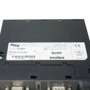
SKU: SST-PB3-CLX-RLL
Allen-Bradley SST-PB3-CLX-RLL | Industrial PROFIBUS DP Scanner