Original Industrial Spare Part
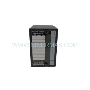
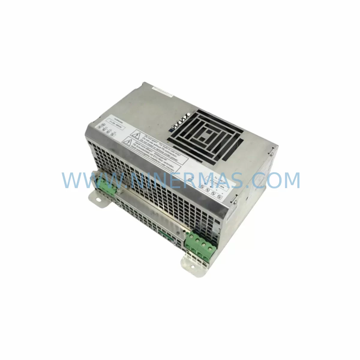
KUKA PH1003-2840 Retrofit-Compatible Power Supply for Legacy Systems
Verify the part, confirm the platform family, and move straight into quotation with the right commercial details.
RFQ Ready
- SKUPH1003-2840
- CategoryPLC & Industrial Automation Modules
- BrandKUKA
- SupportAvailability, lead time, condition, and shipping coordination
How Buyers Usually Use This Page
- Confirm the exact part number and platform family before sending the quote request.
- Use direct email when quantity, condition, and destination are already defined internally.
- Switch to the broader brand or category archive when you need alternates nearby.
Series Navigation
Move through the most common platform families behind this part.
Product RFQ
Send this part directly for quotation.
Include quantity, required condition, destination country, and target delivery timing. Current reference: KUKA PH1003-2840 Retrofit-Compatible Power Supply for Legacy Systems with SKU PH1003-2840.
KUKA PH1003-2840 Retrofit-Compatible Power Supply for Legacy KR C2 / KR C3 Systems
The KUKA PH1003-2840 is a critical power supply module designed for seamless integration into legacy KUKA KR C2 and KR C3 robot controller cabinets. As automation facilities face increasing pressure to extend the operational life of installed robot fleets, the PH1003-2840 serves as a proven retrofit solution — enabling engineers to restore full controller functionality without committing to a full KR C4 or KR C5 platform migration. NINERMAS maintains verified stock of this module with a 12-month warranty, supporting procurement teams that require reliable, long-lifecycle spare parts supply.
When planning a power supply replacement within an existing KR C2 or KR C3 cabinet, engineers must first confirm the input voltage range (typically 3-phase 400 VAC / 50 Hz for European-spec controllers, or 480 VAC for North American installations), the DC bus output capacity, and the physical mounting rail configuration inside the control cabinet. The PH1003-2840 occupies a defined slot within the KUKA controller backplane, and its terminal block layout must be matched against the existing wiring harness before installation. Incorrect terminal mapping is one of the most common causes of extended downtime during power supply retrofits — a pre-installation wiring audit is strongly recommended.
Upgrade Compatibility Table
| Parameter | KR C2 (Legacy) | KR C3 (Legacy) | PH1003-2840 Compatibility |
|---|---|---|---|
| Input Voltage | 3-phase 400 VAC | 3-phase 400 VAC | ✔ Compatible |
| Mounting Interface | DIN rail / cabinet slot | DIN rail / cabinet slot | ✔ Direct fit |
| Communication Protocol | DeviceNet / Interbus | Profibus / EtherCAT | ✔ Power stage independent |
| Backplane Interface | KR C2 backplane connector | KR C3 backplane connector | ⚠ Verify connector pinout |
| Replacement Recommendation | Direct replacement | Direct replacement | ✔ Confirmed |
| Commissioning Note | Re-initialize DC bus after swap | Re-initialize DC bus after swap | Standard procedure |
| Warranty | 12-Month Warranty — NINERMAS COMPANY LIMITED | ||
Retrofit Planning for Existing Automation Systems
A successful PH1003-2840 retrofit begins well before the module arrives on-site. Maintenance engineers should pull the existing controller documentation — including the KR C2 or KR C3 electrical schematic — and cross-reference the power supply slot assignment against the current cabinet layout. In many aging installations, the original KUKA KPS-600 or KPS-27 servo power supply modules may also show signs of wear and should be inspected simultaneously, as a failing power supply often stresses adjacent drive components.
Within the same control cabinet, the KUKA KRC2 DSE-IBS interface board and the KUKA MFC3 motion control card are frequently implicated in cascade failures when the primary power supply degrades. Replacing the PH1003-2840 without auditing these adjacent modules risks a repeat failure within weeks. Similarly, the KUKA RDC (Resolver-to-Digital Converter) board — responsible for axis position feedback — should be verified for stable supply voltage after the new power module is installed.
For facilities running DeviceNet or Profibus field networks, the communication link between the robot controller and the PLC (commonly a Siemens S7-300 or S7-400 series) must be validated post-replacement. A power interruption during the swap can corrupt the node address table stored in the KUKA KRC2 system software, requiring a cold restart and node re-registration. Engineers should back up the robot program and system configuration via the KUKA smartPAD or an offline programming tool before beginning any power supply work.
Where the retrofit is part of a broader I/O expansion — for example, adding additional KUKA KIO I/O modules or integrating a new Beckhoff EK1100 EtherCAT coupler for distributed I/O — the total current draw on the DC bus must be recalculated. The PH1003-2840 has defined output current limits, and exceeding these limits with additional I/O or safety modules will trigger overcurrent protection and halt the robot. A load calculation worksheet should be completed before finalizing the retrofit bill of materials.
Signal isolators — such as the Phoenix Contact MINI MCR-SL series — are often added during KR C2 / KR C3 retrofits to protect analog I/O channels from ground loops introduced by aging cable infrastructure. These isolators should be installed between the robot controller analog outputs and any legacy process instrumentation that has not been replaced as part of the upgrade. Proper shielding and grounding of all signal cables remains essential for maintaining positioning accuracy after the power supply swap.
Downtime Control During System Migration
Minimizing production downtime during a KUKA power supply replacement requires a structured pre-outage preparation protocol. Before the scheduled maintenance window, the full robot program — including all tool data, base data, load data, and safety configuration — must be backed up to an external USB drive or network share. The KUKA WorkVisual project file should also be archived, as it contains the complete I/O mapping, fieldbus configuration, and axis parameterization that will be needed if the controller requires a software restore after the hardware swap.
During the replacement, the DC bus capacitors in the KR C2 or KR C3 drive section must be fully discharged before any internal connections are disturbed. This typically requires a minimum 5-minute wait after main power isolation, verified with a calibrated multimeter at the DC bus terminals. Failure to observe this step creates a serious electrical hazard and can damage the new PH1003-2840 module if residual charge is present during installation.
After the new power supply is seated and all terminal connections are torqued to specification, the controller should be powered up in a controlled sequence: main contactor first, then the 24 VDC logic supply, then the DC bus enable. The KUKA KRC2 boot sequence will perform an internal self-test; any fault codes displayed on the smartPAD should be documented and resolved before releasing the robot to automatic mode. In most straightforward PH1003-2840 replacements, the total planned downtime — from power isolation to robot release — can be held to under four hours when the pre-outage preparation has been completed thoroughly.
For multi-robot cells where a single controller failure affects multiple arms, a staged restart protocol — bringing each robot online individually and verifying its program integrity before enabling the next — reduces the risk of a cell-wide fault cascade. The cell PLC logic should be placed in manual mode during the entire replacement procedure to prevent automatic cycle restarts from triggering while the controller is offline.
Retrofit Support FAQ
Q1: Is the KUKA PH1003-2840 a direct drop-in replacement for the original power supply in my KR C2 controller?
In the majority of KR C2 installations, yes — the PH1003-2840 is designed to fit the original mounting position and terminal layout. However, we recommend confirming the exact cabinet variant (standard, extended, or compact) and the existing wiring harness connector type before ordering. NINERMAS can assist with pre-order compatibility verification based on your controller serial number and cabinet drawing.
Q2: What commissioning steps are required after installing the PH1003-2840?
After physical installation, the DC bus must be re-initialized through the KUKA KRC2 system software. Any axis-specific drive parameters stored in the KUKA KPS servo amplifier modules should be verified against the pre-replacement backup. If the controller displays E-Stop or safety circuit faults after power-up, the safety configuration in the KUKA ESC (Electronic Safety Circuit) board should be re-validated. Full functional testing — including a dry-run of the robot program at reduced speed — is required before returning the cell to production.
Q3: Does NINERMAS provide pre-shipment testing for the PH1003-2840?
Yes. All KUKA PH1003-2840 units shipped by NINERMAS undergo bench-level power-on testing and output voltage verification before dispatch. A test report is available upon request. Units are shipped with ESD-protective packaging and are covered by a 12-month warranty from the date of delivery.
Q4: What is the typical lead time and stock availability?
NINERMAS maintains standing inventory of the PH1003-2840 to support urgent spare-parts requirements. Standard lead time for in-stock units is 3–7 business days for international shipments. For customers requiring long-term supply commitments or blanket orders to support multi-site maintenance programs, NINERMAS offers dedicated stock reservation agreements. Contact our team at sale@ninermas.com or +0086 187 5021 5667 to discuss your procurement requirements.
| Product Series | Legacy |
|---|---|
| Country of Origin | DE |
Catalog Continuation
More KUKA modules in the catalog.
Use the brand lane to compare nearby part numbers, platform-adjacent modules, and other inquiry-ready listings before sending your final RFQ.
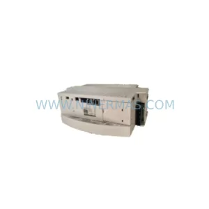
SKU: 033.56.84.10C 033.56.84.10D
KUKA 033.56.84.10C/10D Retrofit-Compatible Gearbox for Legacy Systems
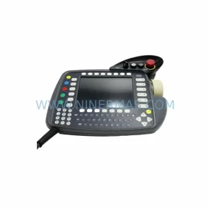
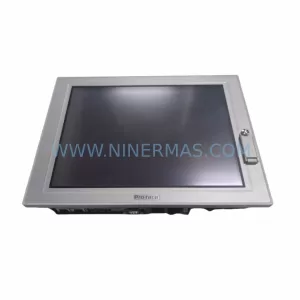
SKU: PFXPP160EA55T00N00
KUKA PFXPP160EA55T00N00 Retrofit-Compatible Teach Pendant for Legacy Systems
Catalog Continuation
Alternative parts within PLC & Industrial Automation Modules.
Stay inside the same system family when you need substitutes, adjacent modules, or a broader shortlist for procurement review.
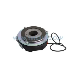
SKU: BFK458-25 (400 N.M) 180VDC
Lenze BFK458-25 400NM 180VDC Service-Ready Spare Part
SKU: 6ES7138-4CF03-0AB0
Siemens 6ES7138-4CF03-0AB0 Service-Ready Spare Part for Industrial Maintenance