Original Industrial Spare Part
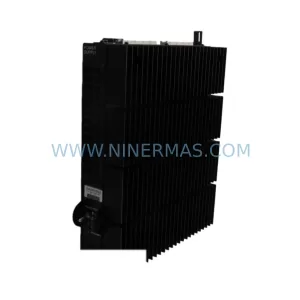
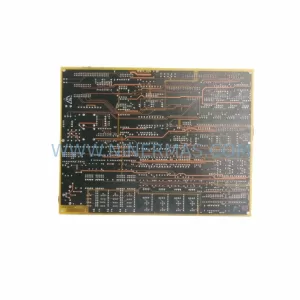
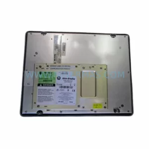
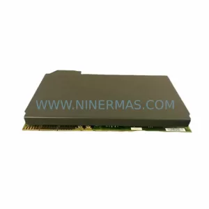
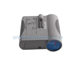
Honeywell FS-PDC-MB24-1P Retrofit-Compatible PDM Legacy Systems
Verify the part, confirm the platform family, and move straight into quotation with the right commercial details.
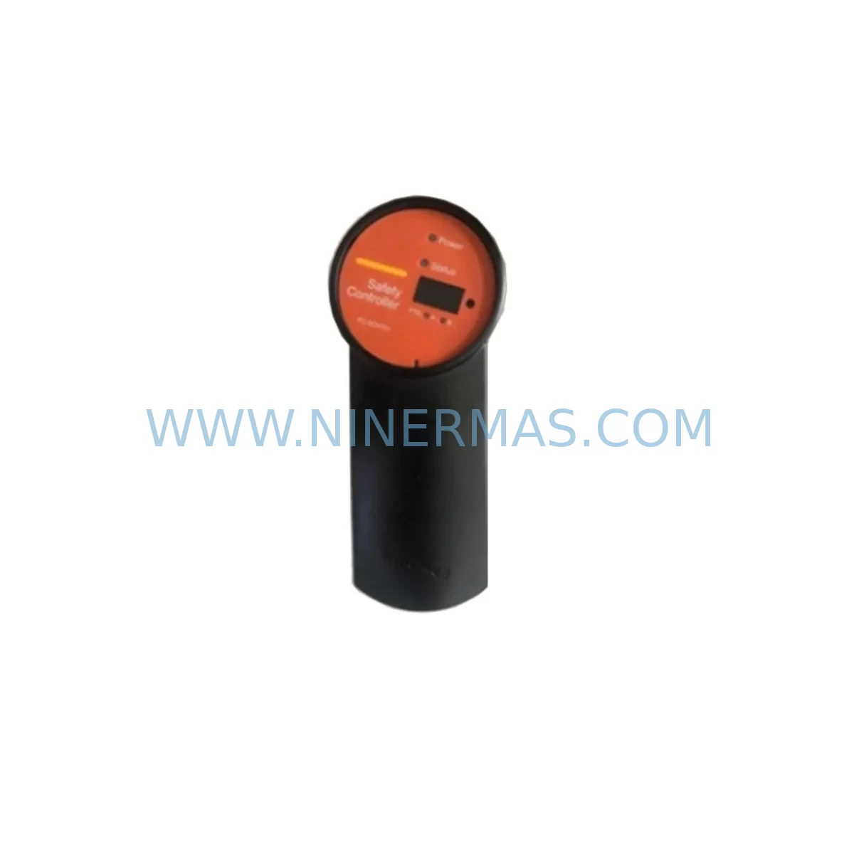
RFQ Ready
- SKUFS-PDC-MB24-1P
- CategorySIS Safety & Redundancy Systems
- BrandHoneywell
- SupportAvailability, lead time, condition, and shipping coordination
How Buyers Usually Use This Page
- Confirm the exact part number and platform family before sending the quote request.
- Use direct email when quantity, condition, and destination are already defined internally.
- Switch to the broader brand or category archive when you need alternates nearby.
Series Navigation
Move through the most common platform families behind this part.
Product RFQ
Send this part directly for quotation.
Include quantity, required condition, destination country, and target delivery timing. Current reference: Honeywell FS-PDC-MB24-1P Retrofit-Compatible PDM Legacy Systems with SKU FS-PDC-MB24-1P.
Honeywell FS-PDC-MB24-1P Retrofit-Compatible PDM Legacy Systems: Seamless Upgrade for Aging Safety Instrumented Systems
The Honeywell FS-PDC-MB24-1P is a 24 VDC single-channel power distribution module engineered for the Honeywell FSC (Fail-Safe Controller) and Safety Manager platform. As legacy safety instrumented systems (SIS) approach end-of-life, the FS-PDC-MB24-1P remains a critical retrofit component for plants seeking to extend operational continuity without a full system overhaul. Whether you are replacing a failed power distribution module in an existing FSC rack, upgrading a control cabinet to meet current IEC 61511 compliance, or migrating from an older Honeywell TDC-3000 safety layer to a modern Safety Manager SC architecture, this module provides the electrical interface and form factor compatibility required for a smooth, low-risk transition.
Sourced directly from authorized distribution channels and verified against original Honeywell manufacturing specifications, each FS-PDC-MB24-1P unit supplied by NINERMAS undergoes pre-shipment functional testing to confirm output voltage stability, terminal integrity, and backplane connector alignment. Inventory is maintained to support urgent spare-part requirements, with standard lead times of 3–7 business days for in-stock units and a 12-month warranty covering manufacturing defects and functional failures under normal operating conditions.
Upgrade Compatibility Table
| Parameter | FS-PDC-MB24-1P Specification | Retrofit / Replacement Notes |
|---|---|---|
| Input Voltage | 24 VDC nominal | Verify cabinet PSU output matches; compatible with FS-PDC-MB24-2P dual-channel variant for redundant configurations |
| Backplane Interface | FSC standard backplane connector | Direct fit into FSC rack slots; confirm rack generation (FSC Mk1 vs Mk2) before installation |
| Installation Form Factor | Standard FSC module width | No mechanical modification required; check slot availability in existing FS-RACK-0014 or equivalent chassis |
| Communication Compatibility | Non-communicating (power only) | No protocol configuration needed; communication handled by FS-SICC-0001 or FS-SICC-0002 interface modules |
| Replacement Recommendation | Direct drop-in for failed or degraded PDC modules | Cross-reference with original Honeywell BOM; confirm part revision level matches installed base |
| Commissioning Focus | Output voltage verification, terminal torque check | Measure 24 VDC at field terminal strip before energizing I/O modules; log readings in site commissioning record |
| 12-Month Warranty | Covered under NINERMAS standard warranty | Applies from date of shipment; covers manufacturing defects and functional failures under rated operating conditions |
Retrofit Planning for Existing Automation Systems
Successful integration of the FS-PDC-MB24-1P into a legacy FSC or Safety Manager system requires a structured pre-retrofit assessment. Engineers should begin by auditing the existing power budget across the control cabinet. The FSC platform distributes 24 VDC to field I/O modules through dedicated power distribution modules; adding or replacing a PDC module without verifying total current draw against the upstream power supply — typically a Honeywell PS-024-060 or equivalent 24 VDC/60 W rail-mount supply — risks nuisance tripping or undervoltage faults on adjacent modules.
Terminal wiring is the next critical checkpoint. The FS-PDC-MB24-1P uses a standard screw-terminal field wiring interface. Before disconnecting the existing module, photograph and document all terminal assignments. Cross-reference against the original loop drawings and the FSC I/O assignment table maintained in the Safety Requirements Specification (SRS). Field wiring connected to analog input modules such as the FS-TSAI-1620M (16-channel thermocouple/mV input) or the FS-SAI-1620M (16-channel standard analog input) must be isolated and tagged before the PDC module is removed to prevent spurious signals from reaching the safety logic solver.
Backplane slot addressing is non-configurable on the FS-PDC-MB24-1P — the module occupies a fixed power slot within the FSC rack. However, engineers must confirm that adjacent logic modules, including the FS-IOM-0001 I/O module and any FS-TSDO-0824 digital output modules, are properly seated and that backplane bus connectors show no signs of oxidation or mechanical damage. A damaged backplane connector is a common root cause of intermittent power faults in aging FSC installations and should be inspected during any PDC replacement activity.
For sites migrating from FSC to Safety Manager SC, the FS-PDC-MB24-1P may be retained in the legacy FSC rack during a phased migration. In this scenario, the FSC rack continues to handle a subset of safety functions while Safety Manager SC modules — including the TC-CCR014 controller module and TC-FPCXX2 field power conditioner — are commissioned in parallel. Communication between the two platforms during the transition period is typically managed through hardwired interlock signals or a dedicated Modbus RTU link via the FS-SICC-0001 serial interface module, avoiding the need to modify the existing FSC program logic until the cutover date.
HMI screen updates are often overlooked during PDC replacement projects. If the plant DCS or safety HMI references power module status tags derived from FSC diagnostics, the HMI engineer must verify that the replacement module’s diagnostic output format matches the original. Honeywell’s FSC diagnostic data is typically surfaced through the FSC Engineering Tool and mapped to the DCS historian via OPC or a dedicated 51309276-150 communication interface card. Confirm that the historian tag mapping remains valid after module replacement and that alarm setpoints for power supply deviation are correctly configured.
Installation space confirmation is straightforward for a like-for-like PDC replacement but becomes more complex when the retrofit involves adding a second power distribution channel. The FS-PDC-MB24-2P dual-channel variant requires the same physical slot width as the single-channel FS-PDC-MB24-1P, but the field terminal block depth may differ depending on the cabinet door clearance. Measure available depth before ordering the dual-channel variant for space-constrained cabinets.
Signal isolation requirements should also be reviewed. Where field loops share a common 24 VDC supply rail with the FSC I/O, a signal isolator — such as a DIN-rail-mounted galvanic isolator compatible with the 10006/2/1 series — may be required to prevent ground loops from affecting SIS measurement accuracy. This is particularly relevant for thermocouple inputs connected to the FS-TSAI-1620M, where common-mode noise can introduce measurement errors that trigger spurious safety actions.
Finally, pre-shipment testing documentation provided with each NINERMAS-supplied FS-PDC-MB24-1P includes output voltage test records and visual inspection reports. Retain these documents as part of the site’s mechanical completion (MC) package for audit purposes.
Downtime Control During System Migration
Minimizing unplanned downtime during a PDC module replacement in a live safety system requires careful sequencing. The recommended approach is to schedule the replacement during a planned maintenance window with the process unit in a safe state. Before initiating the replacement, place the FSC in bypass mode for the affected safety functions in accordance with the site’s Management of Change (MOC) procedure and obtain written authorization from the Safety Instrumented System (SIS) engineer of record.
The existing FSC program logic — stored in the FSC Engineering Tool project file — must be backed up to a secure network location before any hardware changes are made. This backup protects against accidental logic corruption during module handling and provides a recovery baseline if the replacement module exhibits unexpected behavior during commissioning. The backup should include the full project database, I/O configuration, and cause-and-effect matrix.
During the physical swap, maintain field control continuity by confirming that the process is held at a stable operating point or that manual control has been established at the field level. For critical loops, consider deploying portable signal simulators to hold analog inputs at their last valid value while the PDC module is replaced, preventing the FSC from detecting a loss-of-signal fault and initiating an unintended safety action.
After installing the FS-PDC-MB24-1P, perform a staged power-up sequence: energize the module, verify 24 VDC output at the field terminal strip, confirm that all downstream I/O modules return to normal diagnostic status in the FSC Engineering Tool, and then release the bypass. Document the as-found and as-left conditions in the site’s proof test record. Total replacement time for a prepared team with pre-staged materials is typically 30–90 minutes, keeping planned downtime well within a standard maintenance window.
Retrofit Support FAQ
Q1: Is the FS-PDC-MB24-1P a direct replacement for all FSC power distribution module variants?
The FS-PDC-MB24-1P is the single-channel 24 VDC variant. It is a direct replacement for units of the same part number. If your existing installation uses a dual-channel or 48 VDC variant, confirm the exact part number before ordering. NINERMAS technical support can assist with cross-referencing your existing module against available replacement options.
Q2: What commissioning steps are required after installing the replacement module?
After physical installation, verify 24 VDC output voltage at the field terminal strip using a calibrated multimeter. Confirm that all I/O modules powered by the PDC return to normal status in the FSC Engineering Tool. Check that no new diagnostic alarms are present on the FSC controller. Release any bypasses applied during the replacement and perform a functional test of at least one safety function powered by the replaced module before returning the system to normal operation.
Q3: Can the FS-PDC-MB24-1P be used in a Safety Manager SC rack?
No. The FS-PDC-MB24-1P is designed for the FSC rack platform. Safety Manager SC uses a different backplane architecture and dedicated power modules. If you are migrating to Safety Manager SC, the FSC PDC modules remain in the legacy FSC rack during the transition period and are decommissioned when the FSC rack is retired.
Q4: What does the 12-month warranty cover, and how is a warranty claim initiated?
The NINERMAS 12-month warranty covers manufacturing defects and functional failures under rated operating conditions from the date of shipment. It does not cover damage resulting from incorrect installation, overvoltage, or physical mishandling. To initiate a warranty claim, contact NINERMAS at sale@ninermas.com with the original order number, a description of the failure mode, and the pre-shipment test record supplied with the unit. Replacement or repair will be arranged within 5 business days of claim approval.
| Product Series | Safety Manager |
|---|---|
| Country of Origin | US |
Catalog Continuation
More Honeywell modules in the catalog.
Use the brand lane to compare nearby part numbers, platform-adjacent modules, and other inquiry-ready listings before sending your final RFQ.
SKU: 51309218-175 MC-TAMR03
Honeywell 51309218-175 MC-TAMR03 Service-Ready Spare Part
SKU: CC-PDOB01 51405043-176
Honeywell CC-PDOB01 51405043-176 Service-Ready Spare Part
Catalog Continuation
Alternative parts within SIS Safety & Redundancy Systems.
Stay inside the same system family when you need substitutes, adjacent modules, or a broader shortlist for procurement review.