Original Industrial Spare Part
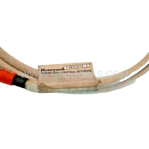
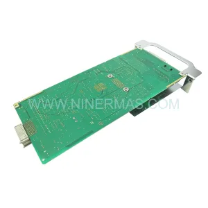
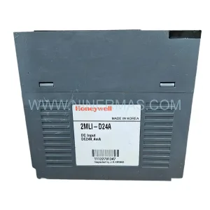
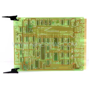
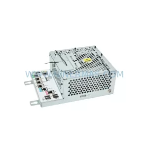
Honeywell FC-SCNT02 Retrofit-Compatible Safety Controller Node
Verify the part, confirm the platform family, and move straight into quotation with the right commercial details.
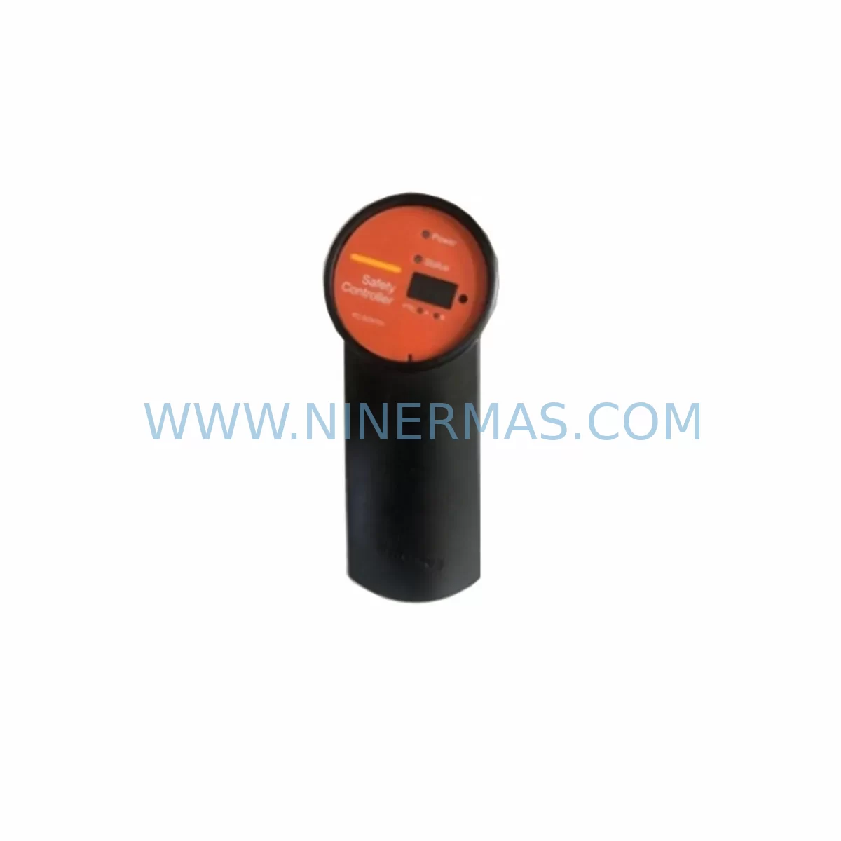
RFQ Ready
- SKUFC-SCNT02 FC-TCNT11 FC-SCNT01 FC-SSWM01 .CC-SDRX01
- CategorySIS Safety & Redundancy Systems
- BrandHoneywell
- SupportAvailability, lead time, condition, and shipping coordination
How Buyers Usually Use This Page
- Confirm the exact part number and platform family before sending the quote request.
- Use direct email when quantity, condition, and destination are already defined internally.
- Switch to the broader brand or category archive when you need alternates nearby.
Series Navigation
Move through the most common platform families behind this part.
Product RFQ
Send this part directly for quotation.
Include quantity, required condition, destination country, and target delivery timing. Current reference: Honeywell FC-SCNT02 Retrofit-Compatible Safety Controller Node with SKU FC-SCNT02 FC-TCNT11 FC-SCNT01 FC-SSWM01 .CC-SDRX01.
Honeywell FC-SCNT02 Retrofit-Compatible Safety Controller Node: Legacy System Compatibility and Smooth Upgrade Path
The Honeywell FC-SCNT02 Safety Controller Node is a core processing module within the Honeywell Safety Manager FC-series platform, designed to execute safety logic, manage I/O communication, and maintain SIL-rated control integrity in process automation environments. As legacy FC-series installations age and original components reach end-of-life, the FC-SCNT02 has become a critical retrofit and replacement target for engineering teams managing safety instrumented systems (SIS) in petrochemical, oil and gas, power generation, and advanced manufacturing facilities.
This module is fully compatible with existing FC-series backplane architectures and can be integrated into operational safety cabinets without requiring a full system redesign. For sites currently running the earlier FC-SCNT01 Safety Controller Node, the FC-SCNT02 represents a direct functional upgrade, offering improved processing throughput and enhanced diagnostic coverage while preserving the original program logic structure and I/O addressing scheme. Engineering teams transitioning from FC-SCNT01 to FC-SCNT02 should verify backplane slot assignments, confirm power rail compatibility, and review the safety application program for any version-specific function block differences before commissioning.
In retrofit scenarios, the FC-SCNT02 is typically deployed alongside the FC-TCNT11 Trusted Communication Node, which manages high-speed peer-to-peer communication between safety controllers across the FC-series network. Maintaining the FC-TCNT11 during a controller node swap is essential to preserve communication link integrity and avoid unintended safety shutdowns during the migration window. Similarly, the FC-SSWM01 Safety Switch Module must remain operational throughout the transition to ensure that manual override and bypass functions continue to respond correctly during the changeover period.
Power supply capacity is a primary verification point in any FC-SCNT02 retrofit. The module draws regulated DC power from the FC-series rack power distribution bus, and sites upgrading from older controller revisions should audit the existing power supply modules to confirm adequate current headroom. If the installation includes expanded I/O racks populated with FC-SDI-1624 digital input modules or FC-SDO-0824 digital output modules, the aggregate power demand must be recalculated to account for any additional modules introduced during the upgrade. Insufficient power margin is a common root cause of intermittent faults during post-retrofit commissioning.
Terminal wiring and field device connections generally do not require modification when replacing the controller node, as the FC-SCNT02 interfaces with field signals through the existing I/O modules rather than directly. However, engineering teams should inspect all terminal blocks and cable shields in the control cabinet for signs of corrosion or mechanical wear before restarting the system, particularly in installations that have been in continuous service for more than ten years. The CC-SDRX01 Serial Data Receiver, where present in the cabinet, should also be inspected and its firmware version confirmed against the compatibility matrix for the FC-SCNT02 revision being installed.
For sites that include FC-TSDI-16UNI universal digital input modules in their I/O configuration, module address settings must be verified after the controller node replacement. The FC-SCNT02 performs automatic I/O module discovery during startup, but address conflicts introduced by hardware changes can prevent correct module recognition. A structured pre-commissioning checklist that covers slot addressing, module type verification, and I/O channel mapping will significantly reduce the risk of extended downtime during the cutover.
HMI screen updates are another consideration in FC-SCNT02 retrofit projects. Control room displays connected to the Safety Manager platform via the FC-QPP02 Qualified Peer Port or through OPC-based historian links may require tag remapping if the controller node replacement is accompanied by a safety application revision. Coordinating HMI updates with the controller cutover, rather than treating them as separate activities, reduces the total commissioning window and minimizes the period during which the safety system operates in a partially verified state.
Communication protocol continuity is maintained through the FC-series network architecture, which supports HART pass-through and Modbus integration at the I/O module level. Sites migrating from older FC-series revisions to current hardware should confirm that all communication links, including those to distributed control systems and asset management platforms, are re-established and verified before returning the safety system to normal operation. The TC-CCR014 communication cable assembly is commonly used in FC-series installations for controller-to-controller links and should be inspected for continuity and shielding integrity as part of the retrofit preparation.
Upgrade Compatibility Table
| Parameter | FC-SCNT01 (Legacy) | FC-SCNT02 (Replacement) | Retrofit Notes |
|---|---|---|---|
| Backplane Interface | FC-Series Standard Backplane | FC-Series Standard Backplane | Direct slot-compatible; no backplane modification required |
| Power Requirement | 24 VDC regulated | 24 VDC regulated | Verify power supply current headroom before installation |
| Communication Protocol | FC-Series peer network | FC-Series peer network | FC-TCNT11 must remain active during cutover |
| Safety Application Compatibility | FC Safety Manager application | FC Safety Manager application | Review function block version compatibility before download |
| I/O Module Addressing | Slot-based auto-discovery | Slot-based auto-discovery | Confirm module addresses post-replacement; check FC-SDI-1624 and FC-SDO-0824 assignments |
| HMI Integration | OPC / FC-QPP02 link | OPC / FC-QPP02 link | Remap HMI tags if safety application revision is included |
| Installation Space | Standard FC-series rack slot | Standard FC-series rack slot | No additional space required; same form factor |
| Commissioning Requirement | Full SIL validation required | Full SIL validation required | Functional safety test must be repeated after replacement |
| Warranty | — | 12 Months | Covers manufacturing defects; pre-shipment tested |
Retrofit Planning for Existing Automation Systems
A structured retrofit plan for FC-SCNT02 installation begins with a comprehensive site survey of the existing FC-series cabinet. The survey should document the current population of all rack-mounted modules, including the FC-SCNT01 or earlier controller node, FC-TCNT11 communication nodes, FC-SSWM01 safety switch modules, FC-SDI-1624 digital input modules, FC-SDO-0824 digital output modules, and FC-TSDI-16UNI universal input modules. Photographing the existing wiring and recording all module slot positions before any hardware is disturbed provides a reliable reference baseline for post-installation verification.
Power supply modules should be load-tested prior to the retrofit to confirm that available current capacity exceeds the combined demand of all installed modules plus a minimum 20% safety margin. If the existing power supply is operating near its rated limit, a replacement or supplementary power module should be sourced and staged before the cutover date. Scheduling the retrofit during a planned maintenance window, rather than responding to an unplanned failure, allows adequate time for pre-commissioning checks and reduces pressure on the engineering team during the critical cutover phase.
The CC-SDRX01 Serial Data Receiver and TC-CCR014 communication cable assemblies should be inspected and tested as part of the pre-retrofit preparation. Any cables showing signs of insulation damage, connector wear, or continuity faults should be replaced before the new FC-SCNT02 is installed. Introducing a new controller node into a cabinet with degraded communication infrastructure increases the risk of intermittent faults that are difficult to diagnose after the fact.
Programming cable availability and laptop configuration for the FC Safety Manager engineering workstation should be confirmed well in advance of the cutover. The safety application program should be backed up from the existing FC-SCNT01 and stored in a version-controlled repository before the old module is removed. This backup serves as the recovery baseline if the new FC-SCNT02 requires a rollback during commissioning.
Downtime Control During System Migration
Minimizing downtime during an FC-SCNT02 replacement requires a pre-approved bypass and inhibit strategy that allows the safety system to be taken out of service in a controlled manner without triggering unplanned process shutdowns. The FC-SSWM01 Safety Switch Module provides the hardware interface for manual bypass operations and should be tested for correct function before the cutover begins. All bypass activations must be documented in the site’s management of change (MOC) system and approved by the responsible safety engineer before work commences.
The original safety application program logic should be preserved without modification during the hardware replacement unless a specific program revision has been approved as part of the same MOC. Combining hardware and software changes in a single cutover increases the complexity of fault isolation if problems arise during commissioning. Where a program revision is necessary, it should be validated in a factory acceptance test (FAT) environment using a spare FC-SCNT02 before being deployed to the live system.
Field control continuity during the migration window can be maintained by confirming that all hardwired safety functions, including emergency shutdown (ESD) loops and fire and gas (F&G) detection circuits, remain active through the existing field wiring even when the controller node is offline. The FC-series architecture supports a defined safe state for all outputs during controller absence, and this behavior should be verified against the process safety requirements before the cutover is authorized.
Post-replacement commissioning should follow a structured test sequence that covers power-on diagnostics, I/O module recognition, communication link establishment with FC-TCNT11 nodes, safety application download and verification, and a full functional safety test of all SIL-rated loops. The total commissioning window for an experienced team with all required tools and documentation on site is typically four to six hours for a single controller node replacement in a well-documented FC-series installation.
Retrofit Support FAQ
Q1: Is the FC-SCNT02 a direct drop-in replacement for the FC-SCNT01?
The FC-SCNT02 is functionally compatible with the FC-SCNT01 and installs in the same backplane slot. However, a direct replacement requires verification of the safety application program for function block compatibility, confirmation of power supply capacity, and a full functional safety test after installation. It is not a plug-and-play swap without engineering review.
Q2: What pre-shipment testing is performed on the FC-SCNT02?
Each FC-SCNT02 unit supplied by NINERMAS undergoes pre-shipment functional testing that includes power-on self-diagnostics, communication interface verification, and I/O channel continuity checks. Units are supplied with a 12-month warranty covering manufacturing defects and are packaged to prevent electrostatic discharge damage during transit.
Q3: Can the FC-SCNT02 be installed without taking the entire FC-series system offline?
In most FC-series configurations, replacing the controller node requires a controlled system shutdown and bypass of the associated safety functions. Hot-swap capability depends on the specific system architecture and the redundancy configuration in use. Engineering teams should consult the Honeywell Safety Manager system documentation and obtain approval through the site MOC process before attempting any live maintenance on safety-rated equipment.
Q4: What is the typical lead time and stock availability for the FC-SCNT02?
NINERMAS maintains reserved inventory of FC-SCNT02 units to support urgent retrofit and breakdown replacement requirements. Standard lead time for in-stock units is two to five business days for international shipment. For sites with planned maintenance schedules, NINERMAS offers long-term supply commitments and reserved stock programs to ensure availability when needed, reducing the risk of extended downtime due to component unavailability.
| Product Series | Safety Manager |
|---|---|
| Country of Origin | US |
Catalog Continuation
More Honeywell modules in the catalog.
Use the brand lane to compare nearby part numbers, platform-adjacent modules, and other inquiry-ready listings before sending your final RFQ.
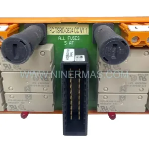
SKU: FC-TSRO-0824 CCV 1.1
Honeywell FC-TSRO-0824 CCV 1.1 SIL3 Relay Output Field Termination Assembly
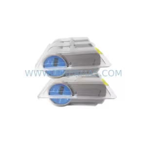
SKU: 51309218-175 MC-TAMR03
Honeywell 51309218-175 MC-TAMR03 Service-Ready Spare Part
Catalog Continuation
Alternative parts within SIS Safety & Redundancy Systems.
Stay inside the same system family when you need substitutes, adjacent modules, or a broader shortlist for procurement review.
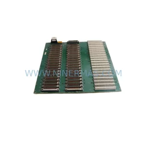
SKU: IS200BPVCG1BR1
GE IS200BPVCG1BR1 Safety-Reliable Board for Critical Control
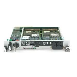
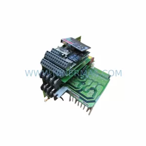
SKU: G85139-H1750-C810-D
Siemens G85139-H1750-C810-D Safety-Reliable Drive Module
SKU: DSQC1000 3HAC042766-001
ABB 3HAC042766-001 Safety-Reliable Robot CPU for Critical Sites