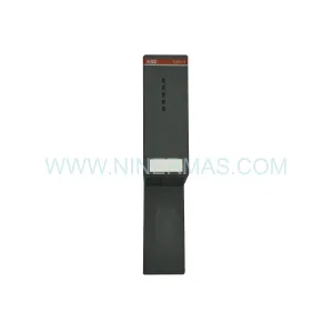
Original Industrial Spare Part
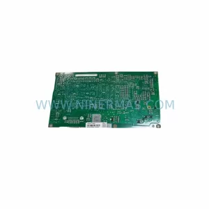
FUJI SHARP Z-312J Retrofit-Compatible Output Module for Legacy PLC
Verify the part, confirm the platform family, and move straight into quotation with the right commercial details.
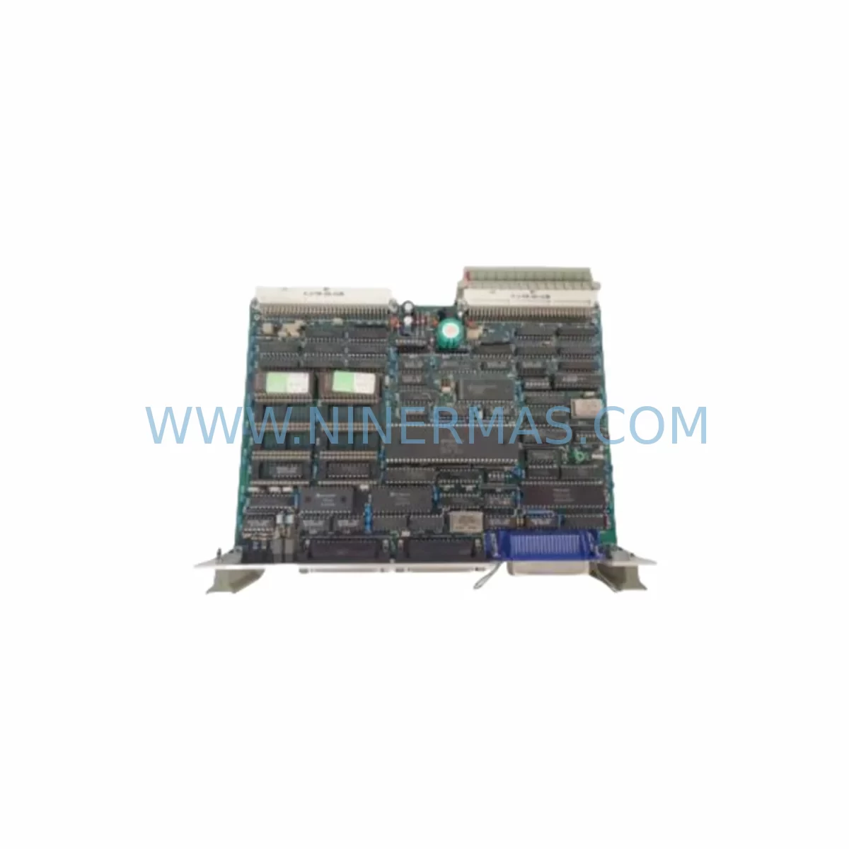
RFQ Ready
- SKUZ-312J
- CategoryPLC & Industrial Automation Modules
- BrandFUJI SHARP
- SupportAvailability, lead time, condition, and shipping coordination
How Buyers Usually Use This Page
- Confirm the exact part number and platform family before sending the quote request.
- Use direct email when quantity, condition, and destination are already defined internally.
- Switch to the broader brand or category archive when you need alternates nearby.
Series Navigation
Move through the most common platform families behind this part.
Product RFQ
Send this part directly for quotation.
Include quantity, required condition, destination country, and target delivery timing. Current reference: FUJI SHARP Z-312J Retrofit-Compatible Output Module for Legacy PLC with SKU Z-312J.
FUJI SHARP Z-312J Retrofit-Compatible Output Module: Seamless Legacy System Integration and Smooth Upgrade Path
The FUJI SHARP Z-312J is a retrofit-compatible output module engineered for the SHARP Series PLC platform — a control architecture widely deployed across discrete manufacturing, packaging lines, material handling systems, and process automation installations throughout the 1980s and 1990s. As original FUJI SHARP SHARP Series hardware reaches end-of-life and OEM spare parts become increasingly scarce, the Z-312J remains one of the most sought-after replacement modules for engineers tasked with sustaining legacy automation infrastructure without committing to a full control system overhaul.
Whether your facility is managing a long-running production line that cannot afford extended downtime, or your maintenance team is executing a phased migration from an aging SHARP Series rack to a modern control platform, the Z-312J provides the output switching capacity and backplane compatibility required to bridge the gap between legacy and contemporary automation architectures.
Upgrade Compatibility Table
| Parameter | FUJI SHARP Z-312J | Retrofit Notes |
|---|---|---|
| Module Type | Digital Output Module | Verify output type (relay/transistor) matches field device requirements |
| Series Compatibility | FUJI SHARP SHARP Series PLC | Confirm backplane slot assignment and rack address before installation |
| Backplane Interface | SHARP Series proprietary backplane connector | Inspect backplane pins for corrosion; replace SHARP Series backplane if damaged |
| Terminal Wiring | Screw-terminal field wiring block | Re-use existing field wiring; verify conductor gauge and torque spec |
| Communication Protocol | Parallel I/O bus (SHARP Series internal) | No protocol migration required for like-for-like replacement |
| Installation Space | Standard SHARP Series single-slot module | Confirm rack slot availability; no panel modification required |
| Program Compatibility | Fully compatible with existing SHARP Series ladder logic | No program modification required for direct replacement |
| HMI Screen Impact | None (output addressing unchanged) | Verify HMI tag mapping if I/O address reassignment is planned |
| Commissioning | Force output test recommended post-installation | Use SHARP Series programming tool to verify output status bits |
| Warranty | 12-Month Warranty — covers manufacturing defects under normal operating conditions | |
Retrofit Planning for Existing Automation Systems
A successful Z-312J retrofit begins well before the module arrives on-site. Maintenance engineers should start by auditing the existing SHARP Series rack configuration — documenting each occupied slot, the module type installed, and the I/O address assignments mapped in the current ladder logic program. This audit prevents address conflicts when the replacement Z-312J is seated and powered.
Power budget verification is a critical pre-installation step. The SHARP Series rack relies on a dedicated SHARP Series power supply module (such as the Z-2PS or equivalent) to distribute regulated DC voltage across the backplane. Before installing the Z-312J, confirm that the existing power supply module has sufficient residual capacity to support the output module’s load current, particularly if other modules have been added to the rack since the original system commissioning. An undersized or aging power supply module is a common root cause of intermittent output faults that are incorrectly attributed to the output module itself.
Terminal wiring adaptation is typically straightforward for a like-for-like Z-312J replacement. The existing field wiring connected to the original module’s screw-terminal block can generally be re-terminated directly to the replacement unit, provided conductor insulation and gauge remain within specification. For installations where the original wiring documentation has been lost, a point-to-point continuity check against the HMI screen tag list or the original I/O schedule is recommended before energizing the system.
In cases where the Z-312J replacement is part of a broader migration from the SHARP Series platform to a contemporary controller — such as a transition to a FUJI MICREX-SX series CPU or a third-party PLC with equivalent I/O density — engineers must also account for communication protocol differences. The SHARP Series uses a proprietary parallel I/O bus architecture that does not natively interface with modern fieldbus protocols such as PROFIBUS-DP, DeviceNet, or EtherNet/IP. A protocol gateway module or a dedicated communication interface module will be required to bridge legacy field devices to the new control platform during the transition period.
For facilities managing a phased migration, it is common to operate the Z-312J alongside newer I/O modules within a hybrid rack configuration. In these scenarios, a SHARP Series I/O expansion module may be used to extend the rack’s I/O capacity while the migration is underway, allowing production to continue on the legacy program while the new control logic is developed and tested offline. Signal isolators — particularly DIN-rail-mounted signal conditioning modules — are frequently added at this stage to protect new controller inputs from legacy field wiring that may carry noise or voltage spikes from aging actuators and solenoids.
HMI screen compatibility should be reviewed early in the planning process. If the existing operator interface is a legacy SHARP Series HMI panel or a standalone operator terminal communicating via RS-232 or RS-422, the screen tag database will reference I/O addresses tied to the SHARP Series CPU. A direct Z-312J replacement preserves these address assignments without modification. However, if the migration plan includes replacing the CPU with a new controller, the HMI tag database will require a full remap, and screen-by-screen functional testing should be scheduled as part of the commissioning plan.
Programming cable access is another practical consideration. The SHARP Series CPU typically requires a dedicated SHARP Series programming cable and compatible programming software to upload, download, or monitor the ladder logic program. Ensure that a functional programming cable and a PC with the correct software version are available on-site before beginning the retrofit, as remote program backup and post-installation verification are essential steps in any controlled replacement procedure.
Downtime Control During System Migration
Minimizing unplanned downtime is the primary operational constraint in any legacy PLC retrofit. For the Z-312J replacement, the most effective downtime reduction strategy is a pre-staged swap: the replacement module is received, inspected, and bench-tested against a known-good SHARP Series rack before the scheduled maintenance window. This eliminates the risk of discovering a transit-damaged or incompatible module during a live production outage.
Before removing the original Z-312J from the rack, the existing ladder logic program should be uploaded from the SHARP Series CPU and saved to at least two independent storage locations — a local PC and a removable storage device. This program backup protects against data loss in the event that the CPU battery has discharged or the program memory has been corrupted by the fault condition that necessitated the module replacement.
During the physical swap, the rack should be de-energized at the power supply module level rather than at the main panel disconnect, where possible. This approach preserves the CPU’s program memory and retains the current I/O address configuration, reducing the time required to restore normal operation after the replacement module is seated. Once the Z-312J is installed and the rack is re-energized, a systematic output force test — conducted from the programming terminal with field devices in a safe state — confirms that each output channel is switching correctly before the system is returned to automatic mode.
For facilities where continuous production is required and a cold-swap is not feasible, a parallel redundancy approach may be considered: a temporary bypass relay panel is wired in parallel with the affected output channels, allowing the process to continue under manual control while the module replacement is performed. This approach requires careful coordination between the automation engineer and the operations team to ensure that manual control interlocks are correctly implemented and that the bypass is removed cleanly after the replacement is verified.
Post-replacement, a 24-hour monitoring period is recommended during which the SHARP Series CPU’s diagnostic registers and the Z-312J’s output status indicators are checked at regular intervals. Any recurrence of the original fault condition should be investigated at the field device level — actuator coil resistance, solenoid valve condition, and output load current — before concluding that the replacement module is defective.
Retrofit Support FAQ
Q1: Is the FUJI SHARP Z-312J a direct drop-in replacement for the original module, or are wiring modifications required?
For like-for-like replacement within the same SHARP Series rack, the Z-312J is a direct drop-in replacement. The backplane connector, slot dimensions, and I/O address assignment are preserved, and existing field wiring can be re-terminated to the replacement module’s screw-terminal block without modification. No changes to the ladder logic program or HMI screen database are required.
Q2: What commissioning steps are required after installing the Z-312J?
After seating the module and restoring power to the rack, connect the SHARP Series programming cable and use the programming software to verify that the CPU recognizes the Z-312J in the correct slot. Perform a forced output test on each channel with field devices in a safe state to confirm correct switching. Check the CPU’s I/O error register for any fault codes before returning the system to automatic operation.
Q3: Can the Z-312J be used in a hybrid rack alongside newer FUJI MICREX-SX or third-party I/O modules?
The Z-312J is designed for the SHARP Series proprietary backplane and is not directly interchangeable with MICREX-SX or other platform-specific modules. In a phased migration scenario, the SHARP Series rack and the new control platform operate as separate subsystems, with data exchange handled via a communication interface module or protocol gateway. Direct mixing of SHARP Series and MICREX-SX modules in the same rack is not supported.
Q4: What does the 12-month warranty cover, and what is the supply lead time?
The Z-312J carries a 12-month warranty covering manufacturing defects under normal operating conditions. Warranty claims require the module to be returned for inspection; field-damaged or incorrectly installed units are not covered. Stock is maintained for prompt dispatch; typical lead time for in-stock units is 3–7 business days depending on destination. For urgent requirements, expedited shipping options are available — contact our team directly to confirm current inventory status and dispatch schedule.
| Product Series | Other series |
|---|
Catalog Continuation
Alternative parts within PLC & Industrial Automation Modules.
Stay inside the same system family when you need substitutes, adjacent modules, or a broader shortlist for procurement review.
SKU: 6FC5357-0BB12-0AE0
Siemens 6FC5357-0BB12-0AE0 Service-Ready Industrial Spare Part
SKU: 3BSE011790R1(PXHK401)
ABB 3BSE011790R1 PXHK401 Retrofit-Ready Communication Module