Original Industrial Spare Part
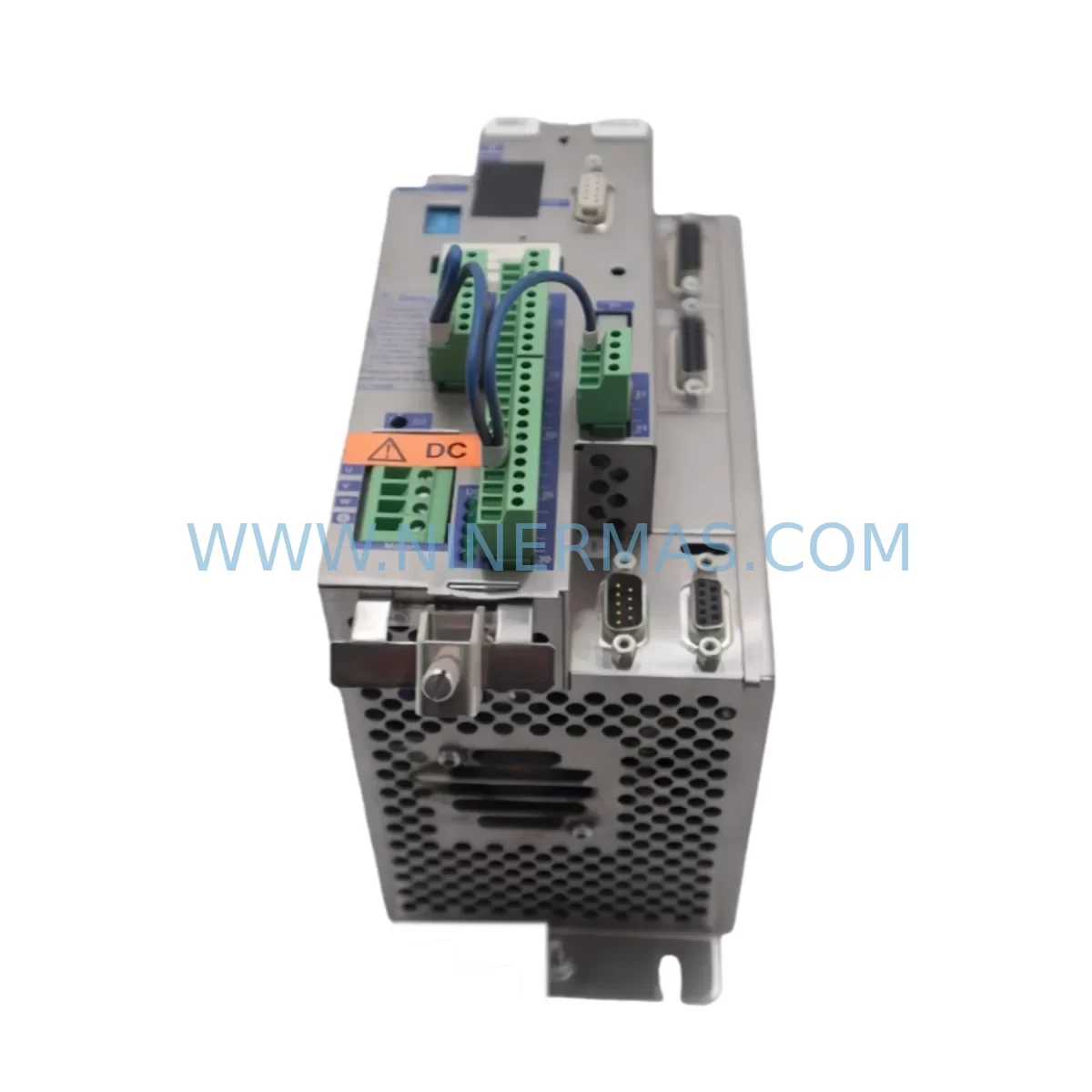
BERGER LAHR TLC511 F Retrofit-Compatible Servo Drive for Legacy Systems
Verify the part, confirm the platform family, and move straight into quotation with the right commercial details.
RFQ Ready
- SKUTLC511 F
- CategoryPLC & Industrial Automation Modules
- BrandBerger Lahr
- SupportAvailability, lead time, condition, and shipping coordination
How Buyers Usually Use This Page
- Confirm the exact part number and platform family before sending the quote request.
- Use direct email when quantity, condition, and destination are already defined internally.
- Switch to the broader brand or category archive when you need alternates nearby.
Series Navigation
Move through the most common platform families behind this part.
Product RFQ
Send this part directly for quotation.
Include quantity, required condition, destination country, and target delivery timing. Current reference: BERGER LAHR TLC511 F Retrofit-Compatible Servo Drive for Legacy Systems with SKU TLC511 F.
BERGER LAHR TLC511 F Retrofit-Compatible Servo Drive for Legacy Systems
The BERGER LAHR TLC511 F is a ruggedized servo drive module engineered for demanding industrial environments and designed to serve as a reliable retrofit solution for aging automation systems. As legacy motion control platforms reach end-of-life and OEM support is discontinued, the TLC511 F provides a proven upgrade path that preserves existing wiring infrastructure, minimizes reprogramming effort, and reduces total downtime during system migration. Whether you are replacing a failed drive in a production line, upgrading a control cabinet, or extending the operational life of a BERGER LAHR servo platform, the TLC511 F delivers the performance and compatibility required for a smooth transition.
NINERMAS maintains verified inventory of the TLC511 F with full functional testing, 12-month warranty coverage, and rapid dispatch to support time-critical maintenance and retrofit projects worldwide.
Upgrade Compatibility Table
| Parameter | Details |
|---|---|
| SKU / Part Number | TLC511 F |
| Brand / Series | BERGER LAHR / TLC Series |
| Product Type | Servo Drive Module |
| Typical Replacement For | BERGER LAHR TLC511, TLC512, TLC510 series and compatible legacy servo drives |
| Communication Compatibility | RS-232 / RS-485 serial interface; compatible with BERGER LAHR motion controllers and third-party PLC command interfaces |
| Installation Format | Panel / cabinet mount; confirm existing mounting footprint and terminal pitch before installation |
| Power Supply Requirement | Verify input voltage range and DC bus capacity against existing cabinet power supply (e.g., BERGER LAHR STA or STB series power modules) |
| I/O Interface | Digital I/O terminals; confirm signal voltage levels and terminal block wiring compatibility with existing harness |
| Backplane / Rack Interface | Standalone module; verify connector type and backplane slot assignment if integrated into a multi-axis rack |
| Programming / Configuration | Compatible with BERGER LAHR programming tools; parameter migration from legacy drive recommended before commissioning |
| HMI Screen Compatibility | Existing HMI tag mapping should be verified; drive status variables may require remapping if HMI was configured for an earlier firmware revision |
| Commissioning Notes | Confirm motor encoder feedback type, axis address assignment, and enable signal logic before powering up |
| Warranty | 12 Months — Full functional warranty from NINERMAS |
| Testing | Pre-shipment functional test performed on every unit |
| Origin | Germany (DE) |
Retrofit Planning for Existing Automation Systems
Integrating the BERGER LAHR TLC511 F into an existing automation system requires a structured approach to ensure compatibility across every layer of the control architecture. Before beginning the physical swap, engineers should audit the current cabinet layout to confirm available installation space, terminal block configuration, and cable routing clearance. In multi-axis systems where the TLC511 F shares a control cabinet with other BERGER LAHR drives such as the TLC512 or TLC510, it is essential to verify that the shared DC bus or power distribution rail can support the combined load after the retrofit.
Power supply compatibility is a critical first checkpoint. Many legacy BERGER LAHR installations rely on dedicated servo power modules — such as units from the BERGER LAHR STA or STB power supply series — to deliver regulated DC bus voltage to the drive. Before installing the TLC511 F, confirm that the existing power module’s output capacity, inrush current handling, and regenerative braking capability are sufficient for the replacement drive’s rated load. If the original power supply is also approaching end-of-life, a simultaneous upgrade may be advisable to avoid a secondary failure shortly after the servo drive retrofit.
Terminal wiring is another area requiring careful attention. The TLC511 F uses a defined terminal block layout for motor power, encoder feedback, digital I/O, and enable signals. When replacing an older TLC-series drive, technicians should compare the terminal assignments of the legacy unit against the TLC511 F wiring diagram to identify any pin remapping requirements. Signal isolation may be needed at the I/O interface if the replacement drive operates at a different logic voltage level than the original — in such cases, a signal isolator module or interposing relay can be inserted between the PLC output card and the drive’s digital input terminals without modifying the existing PLC program.
For systems where the TLC511 F communicates with a host PLC or motion controller via RS-232 or RS-485 serial link, the communication parameters — baud rate, parity, stop bits, and device address — must be configured to match the existing network settings. If the legacy drive used a proprietary BERGER LAHR motion bus protocol, verify that the TLC511 F firmware revision supports the same command set. In installations where a BERGER LAHR programming cable or PC-based configuration tool was used to set up the original drive, the same toolchain can typically be used to upload a saved parameter file to the TLC511 F, significantly reducing commissioning time.
I/O expansion is a common requirement during retrofit projects. If the existing system uses a remote I/O module or distributed I/O rack connected to the servo drive’s digital inputs, confirm that the I/O module’s output signal type (sourcing or sinking) is compatible with the TLC511 F input circuit. In cases where the original drive included onboard analog I/O for speed reference or torque command signals, verify that the TLC511 F analog input specifications — voltage range, resolution, and impedance — match the signal source, whether that is a PLC analog output card, a signal conditioner, or a process controller.
HMI screen compatibility should be reviewed before going live. If the plant’s HMI panel — whether a standalone operator terminal or a SCADA-connected display — was configured to read drive status registers, fault codes, or axis position data from the legacy TLC-series drive, the tag addresses and data types may need to be updated to reflect the TLC511 F’s register map. This is particularly important in systems where the HMI communicates directly with the drive over a serial link rather than through the PLC. Updating the HMI project file before the physical swap allows the commissioning team to validate screen functionality during the first power-up without additional delays.
Finally, if the retrofit involves replacing multiple drives across a multi-axis servo rack or backplane assembly, plan the sequence of replacements to maintain partial system operation where possible. Replacing one axis at a time, validating each drive independently before proceeding to the next, is the recommended approach for minimizing production impact and isolating any axis-specific commissioning issues.
Downtime Control During System Migration
Unplanned downtime is the primary risk in any servo drive replacement project, and the BERGER LAHR TLC511 F retrofit process is designed to minimize exposure through advance preparation and structured commissioning. The most effective downtime reduction strategy begins before the replacement unit arrives on site: back up the existing drive’s parameter set using the available programming tool, document all terminal wiring with photographs and a written record, and prepare a commissioning checklist that covers axis address assignment, encoder feedback verification, motor direction confirmation, and enable signal logic testing.
Where the production schedule allows, a bench test of the TLC511 F prior to installation is strongly recommended. Connect the drive to a representative power supply, attach a test motor or load simulator, and verify that the unit responds correctly to enable commands, speed references, and fault reset signals before it enters the cabinet. NINERMAS performs a pre-shipment functional test on every TLC511 F unit, but a site-level bench test provides an additional layer of confidence and allows the commissioning team to familiarize themselves with the drive’s behavior before working under time pressure on the production floor.
During the physical swap, protect the existing PLC program and HMI project by placing the control system in a safe state — with all outputs disabled and the relevant axis in a controlled stop condition — before disconnecting the legacy drive. If the system uses a safety relay module or hardwired emergency stop circuit connected to the drive’s STO (Safe Torque Off) input, verify that the safety circuit remains intact and functional after the replacement. Do not bypass or temporarily disable safety interlocks during the retrofit, even under time pressure.
After installation, perform a controlled first power-up with the motor uncoupled from the mechanical load where possible. Verify drive status indicators, confirm that no fault codes are active, and test the enable and disable sequence before commanding any motion. Once basic functionality is confirmed, reconnect the load and perform a slow-speed jog test to verify encoder feedback direction and motor phasing. Only after successful low-speed validation should the system be returned to automatic mode and normal production speed. This structured approach consistently delivers the shortest total downtime while protecting both the equipment and the existing control program logic.
Retrofit Support FAQ
Q1: Is the BERGER LAHR TLC511 F a direct drop-in replacement for the TLC511 or TLC512?
The TLC511 F shares the same TLC series platform as the TLC511 and TLC512 and is designed for compatibility within the BERGER LAHR TLC drive family. However, customers should verify terminal wiring assignments, communication parameter settings, and encoder feedback configuration against their specific installation before completing the swap. NINERMAS technical support can assist with compatibility verification based on your existing drive documentation.
Q2: What commissioning steps are required after installing the TLC511 F?
After physical installation, configure the drive’s axis address, communication parameters, and I/O logic to match the existing system settings. Upload the saved parameter file from the legacy drive if available, or manually enter the required motion parameters. Perform a bench-level enable test, then a slow-speed uncoupled jog test, before returning the axis to full automatic operation. Verify HMI tag mapping and fault code display before signing off on the retrofit.
Q3: Does NINERMAS provide pre-shipment testing and warranty coverage for the TLC511 F?
Yes. Every BERGER LAHR TLC511 F unit shipped by NINERMAS undergoes a functional test prior to dispatch to confirm basic drive operation. All units are covered by a 12-month warranty from the date of shipment. Warranty support includes technical assistance for installation and commissioning issues as well as unit replacement in the event of a confirmed hardware defect.
Q4: What if my existing wiring or cabinet layout is not compatible with the TLC511 F?
If terminal pitch, connector type, or cabinet mounting dimensions differ from the legacy drive, adaptation options include custom terminal adapter plates, interposing relay modules for I/O signal conversion, and signal isolators for analog reference channels. NINERMAS can advise on common adaptation solutions based on your cabinet drawings and existing wiring documentation. Contact our technical team before ordering if you have specific installation constraints.
| Product Series | Legacy |
|---|---|
| Country of Origin | US |
Catalog Continuation
More Berger Lahr modules in the catalog.
Use the brand lane to compare nearby part numbers, platform-adjacent modules, and other inquiry-ready listings before sending your final RFQ.
Catalog Continuation
Alternative parts within PLC & Industrial Automation Modules.
Stay inside the same system family when you need substitutes, adjacent modules, or a broader shortlist for procurement review.
SKU: SCE906A2-002-01 SCE906A200201
Pacific Scientific SCE906A2-002-01 Retrofit Servo Amplifier
SKU: EPC500 3183062451
Alfa Laval EPC500 3183062451 Service-Ready Spare Part