Original Industrial Spare Part
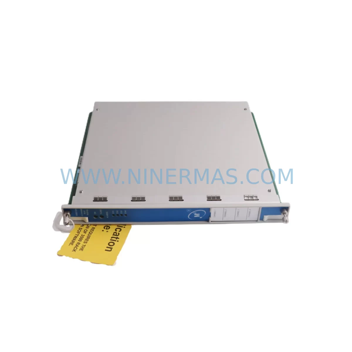
Bently Nevada 3500/32M 149986-02 Retrofit-Compatible Relay Module
Verify the part, confirm the platform family, and move straight into quotation with the right commercial details.
RFQ Ready
- SKU3500/32M 149986-02
- CategoryTSI & Rotating Machinery Monitoring
- BrandBently Nevada
- SupportAvailability, lead time, condition, and shipping coordination
How Buyers Usually Use This Page
- Confirm the exact part number and platform family before sending the quote request.
- Use direct email when quantity, condition, and destination are already defined internally.
- Switch to the broader brand or category archive when you need alternates nearby.
Series Navigation
Move through the most common platform families behind this part.
Product RFQ
Send this part directly for quotation.
Include quantity, required condition, destination country, and target delivery timing. Current reference: Bently Nevada 3500/32M 149986-02 Retrofit-Compatible Relay Module with SKU 3500/32M 149986-02.
Bently Nevada 3500/32M 149986-02 Retrofit-Compatible Relay Module: Seamless Legacy System Upgrade
The Bently Nevada 3500/32M 149986-02 is a ruggedized relay output module engineered for the 3500 Series Machinery Protection System. As original equipment reaches end-of-life and spare parts become increasingly scarce, this module serves as a critical retrofit solution for facilities operating legacy vibration monitoring and machinery protection infrastructure. Whether you are replacing a failed unit, extending the service life of an existing 3500 rack, or migrating from an older Bently Nevada platform, the 3500/32M 149986-02 delivers the relay switching performance and environmental resilience required for continuous industrial operation.
Designed to mount directly into the standard 3500 series rack backplane, this module supports four relay output channels, each configurable for normally open or normally closed operation. The relay contacts are rated for both AC and DC switching loads, making the module compatible with a wide range of alarm annunciators, shutdown logic circuits, and DCS input cards. Its ruggedized construction addresses the demands of harsh plant environments including high vibration, wide temperature swings, and elevated humidity — conditions common in rotating machinery applications such as compressors, turbines, pumps, and fans.
Upgrade Compatibility Table
| Parameter | 3500/32M 149986-02 | Retrofit Notes |
|---|---|---|
| Module Type | Relay Output Module (4-channel) | Direct replacement for earlier 3500/32 variants |
| Rack Compatibility | 3500 Series Standard Rack (3500/05) | Verify slot assignment and backplane revision |
| Relay Contact Rating | 2A @ 30 VDC / 0.5A @ 125 VAC | Confirm load compatibility before wiring |
| Terminal Wiring | Removable I/O terminal block | Re-use existing field wiring where possible |
| Communication Interface | Internal rack bus (non-networked) | No protocol change required |
| Installation Space | Single-width rack slot | No mechanical modification needed |
| Configuration Tool | System 1 / Rack Configuration Software | Backup existing config before module swap |
| Firmware | Factory-loaded, field-upgradeable | Confirm firmware version compatibility |
| Operating Temperature | -20°C to +70°C | Suitable for most plant environments |
| Warranty | 12 Months | Covered from date of shipment |
Retrofit Planning for Existing Automation Systems
Successful integration of the 3500/32M 149986-02 into an existing machinery protection system begins with a thorough pre-replacement audit. Engineers should document the current slot configuration of the 3500/05 rack, noting the position of adjacent modules such as the 3500/15 Power Supply, 3500/20 Rack Interface Module, and any 3500/40M or 3500/42M proximity transducer input modules that share the same rack. Understanding the relay output assignments — which channels drive which shutdown or alarm functions — is essential before any physical swap is attempted.
Terminal wiring is one of the most time-sensitive steps in the retrofit process. The 3500/32M uses a removable terminal block, which allows field wiring to be disconnected from the old module and reconnected to the replacement unit without cutting conductors. Technicians should photograph or sketch the existing wiring layout, verify conductor labeling, and cross-reference against the original loop drawings before proceeding. Where wiring documentation is incomplete or outdated, a point-to-point continuity check against the DCS marshalling cabinet or the associated safety relay panel is strongly recommended.
Backplane interface integrity should be confirmed by inspecting the rack connector pins for corrosion or mechanical damage. In racks that have been in service for more than ten years, it is advisable to also inspect the 3500/20 Rack Interface Module for communication faults, as a degraded RIM can cause false diagnostics on newly installed relay modules. If the facility uses a System 1 condition monitoring platform, the existing machine train configuration and relay setpoint data should be exported and archived before the module is removed.
For sites that are simultaneously upgrading their control network, the relay output module retrofit can be coordinated with a broader migration from legacy serial communication to Ethernet-based architectures. In such cases, the 3500/92 Communication Gateway or a compatible Modbus TCP interface module may be introduced into the rack alongside the 3500/32M replacement, enabling integration with modern DCS platforms such as Emerson DeltaV or Honeywell Experion without requiring a full system replacement. HMI screens that display relay status and alarm states should be updated to reflect any changes in channel mapping or tag naming conventions resulting from the module swap.
I/O expansion requirements should also be evaluated at the planning stage. If the existing relay output capacity is insufficient for new shutdown logic requirements, additional 3500/32M modules can be installed in available rack slots, provided the 3500/15 Power Supply module has sufficient capacity to support the additional load. Power budget calculations should account for all installed modules including transducer input cards, the communication module, and any 3500/61 or 3500/62 temperature input modules present in the rack.
Downtime Control During System Migration
Minimizing unplanned downtime during a relay module replacement requires a structured change management approach. The recommended practice is to schedule the swap during a planned maintenance window, coordinating with operations to confirm that the associated machine train can be safely taken offline or placed in a bypass condition for the duration of the work. Where continuous operation is required, a temporary hardwired bypass of the relay output circuit — using a dedicated bypass relay panel — can maintain shutdown logic continuity while the module is exchanged.
Before removing the 3500/32M from the rack, the technician should place the rack in configuration mode using the Rack Configuration Software to prevent spurious trip signals during the module extraction. The existing module configuration file should be loaded onto the replacement unit prior to installation, reducing on-site programming time and the risk of setpoint entry errors. After the new module is seated and the terminal block reconnected, a functional test of each relay channel should be performed by simulating the corresponding alarm or danger condition at the transducer input and verifying that the relay contact changes state as expected.
Loop checks should be conducted in coordination with the DCS or safety system operator to confirm that relay output signals are received correctly at the destination — whether that is a hardwired shutdown solenoid, an annunciator panel, or a digital input card on a PLC or safety instrumented system. Any discrepancies in signal polarity, contact configuration, or timing should be resolved before the machine train is returned to service. Commissioning records, including as-found and as-left relay setpoints, contact resistance measurements, and functional test results, should be documented and retained for regulatory and maintenance history purposes.
Retrofit Support FAQ
Q: Is the 3500/32M 149986-02 a direct drop-in replacement for earlier 3500/32 relay module variants?
A: In most cases, yes. The 3500/32M 149986-02 is mechanically and electrically compatible with the standard 3500 series rack slot. However, customers should verify the backplane revision of their existing rack and confirm that the relay channel configuration matches their current wiring and setpoint assignments before installation. Our technical team can assist with compatibility verification prior to shipment.
Q: What configuration software is required to commission the replacement module?
A: The 3500/32M 149986-02 is configured using Bently Nevada’s Rack Configuration Software, which communicates with the rack via the 3500/20 Rack Interface Module. Customers should ensure they have a compatible software version installed and that the existing machine configuration file is backed up before beginning the replacement procedure. If the original configuration file is unavailable, our team can assist with parameter reconstruction based on the original system documentation.
Q: Do you provide pre-shipment testing and what does the 12-month warranty cover?
A: Yes. Every 3500/32M 149986-02 unit undergoes functional testing prior to shipment, including relay contact operation verification and communication interface checks. The 12-month warranty covers manufacturing defects and functional failures under normal operating conditions from the date of shipment. It does not cover damage resulting from incorrect installation, overvoltage conditions, or physical mishandling. Warranty claims are supported with direct technical assistance and expedited replacement where required.
Q: What is the typical lead time and do you maintain stock for urgent replacement requirements?
A: We maintain inventory of the 3500/32M 149986-02 to support urgent replacement and emergency breakdown scenarios. Standard orders are processed and shipped within 1-3 business days. For critical plant situations requiring same-day dispatch, please contact our sales team directly to confirm current stock availability and arrange priority shipment.
| Product Series | 3500 series |
|---|---|
| Country of Origin | US |
Catalog Continuation
More Bently Nevada modules in the catalog.
Use the brand lane to compare nearby part numbers, platform-adjacent modules, and other inquiry-ready listings before sending your final RFQ.
SKU: 330910-00-11-10-01-00
Bently Nevada 330910-00-11-10-01-00 Safety-Reliable Proximity Transducer
SKU: 330881-16-00-175-00-02
Bently Nevada 330881-16-00-175-00-02 Safety Proximity Transducer
SKU: 330103-00-10-05-01-00
Bently Nevada 330103-00-10-05-01-00 Retrofit Proximity Probe
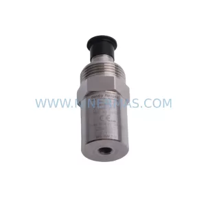
SKU: 190501-06-00-04
Bently Nevada 190501-06-00-04 Retrofit Velocity Transducer
Catalog Continuation
Alternative parts within TSI & Rotating Machinery Monitoring.
Stay inside the same system family when you need substitutes, adjacent modules, or a broader shortlist for procurement review.
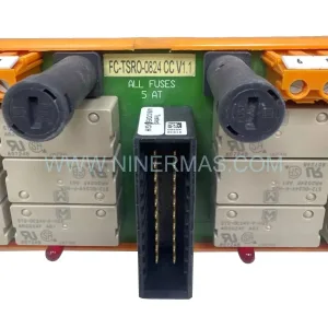
SKU: FC-TSRO-0824 CCV 1.1
Honeywell FC-TSRO-0824 CCV 1.1 SIL3 Relay Output Field Termination Assembly
SKU: 330103-11-19-10-02-00
Bently Nevada 330103-11-19-10-02-00 3300 Series Retrofit
SKU: 21000-16-05-00-115-03-02
Bently Nevada 21000-16-05-00-115-03-02 Retrofit Proximity Probe