A temperature channel can be stable, believable and wrong. That combination is expensive because it encourages a team to adjust a process around the reading instead of questioning the measurement. When an RTD circuit develops an offset after a cable repair or terminal replacement, the input module is only one possible cause. The useful first question is not which module can ship fastest, but which part of the measurement path has changed.
This engineering guide focuses on lead-wire evidence around an installed ControlLogix RTD input. It is not a new product announcement or a live wiring procedure. Any testing that could affect control, alarms or protection belongs within the plant’s approved isolation and instrument-maintenance process.
Draw the complete resistance path
An RTD measurement starts at the sensing element but reaches the input through conductors, connectors, junction boxes and terminal contacts. A drawing that stops at the probe symbol hides several places where an error can enter. Record the actual conductor arrangement from the sensor head to the module, including intermediate joints and any recent work. Do not infer the circuit solely from cable colors or the number of terminals visible at one end.
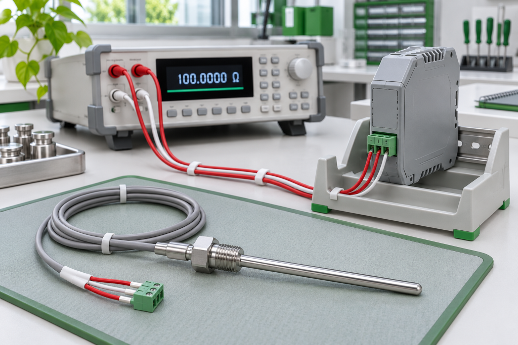
Omega’s RTD wiring explanation describes how lead resistance affects the reading and how compensation arrangements depend on the instrumentation and wiring. In a three-wire arrangement, unequal lead resistance can leave a measurement error. Three conductors are therefore evidence of a wiring arrangement, not proof that all unwanted resistance has disappeared.
For an installation using the Allen-Bradley 1756-IR6I RTD input module, retain the exact module identity with the terminal drawing and channel configuration. The module’s own manual determines the supported connection method. Descriptive wording in a sales listing is not evidence of functional-safety certification and should not be used to qualify a safety function.
Separate an offset from a drifting process
Start with the time history. Did the deviation appear immediately after a terminal was disturbed, gradually through a season, or only when nearby equipment ran? Record whether neighboring channels changed at the same time. A constant difference, intermittent step and slow thermal response are different observations; calling all three a calibration problem loses useful evidence.
Use an independent reference only when its placement, response and uncertainty make the comparison meaningful. Two probes in different parts of a vessel can report different temperatures without either being defective. Write down where the reference was located, when readings were taken and whether the process had stabilized. A photograph of two displays is not a complete comparison record.
Preserve the as-found channel settings before any approved adjustment. Sensor selection, engineering units, scaling and filtering belong in that record. Otherwise a repaired wiring fault and a changed software offset may cancel each other temporarily, leaving the next technician with a plausible but undocumented result.
Use two boundaries for a useful test
A qualified instrument technician can design a controlled test that distinguishes the input channel from the field circuit. One boundary is the module input; the other includes the field wiring. The exact method, isolation, test equipment and restoration steps must follow the applicable manufacturer instructions and site procedure. This article does not prescribe terminal substitutions or permit disconnecting an active process input.
The important reporting rule is simple: name the boundary that was tested. A satisfactory result with a reference applied near the cabinet does not validate the remote probe or cable. Conversely, a field-circuit discrepancy does not by itself prove that the input electronics are damaged. Record the test instrument identity, reference values, conditions and results so another reviewer can follow the conclusion.
Rockwell Automation’s ControlLogix analog I/O manual provides module-specific connection and calibration information. Use the section for the installed catalog number rather than transferring a thermocouple instruction or another RTD module’s terminal arrangement to this circuit.
A replacement decision needs an error budget
Before ordering, agree on what accuracy the process actually requires. The allowed total uncertainty includes more than the module specification: the sensor, installation, wiring, reference instrument and test conditions also matter. The maintenance team should identify which contribution is supported by evidence and which remains unknown. A tighter catalog specification cannot repair an unverified installation.
The 1756-IRT8I temperature-input module is a separate sourcing item, not a substitute to approve from a similar name. Moving between module families requires review of channel arrangement, wiring, project support, configuration and the application’s acceptance criteria. Keep that engineering decision separate from the commercial question of whether a supplier can identify the requested unit.
A practical release package contains the installed module label, channel and terminal references, sensor details, as-found symptoms, approved test results and the required acceptance limits. Ask for unit-specific condition and identification evidence with the quotation. Availability, delivery and suitability should be confirmed explicitly; a public product page does not establish them.
Frequently asked questions
Does a three-wire RTD eliminate every cable error?
No. Compensation depends on the intended circuit and appropriate lead characteristics. Unequal resistance or a poor connection can still affect the result. Confirm the actual wiring and the instrument manufacturer’s requirements rather than treating conductor count as an accuracy guarantee.
Can a software offset solve a new temperature discrepancy?
Not responsibly without a diagnosis and approved calibration decision. An offset can conceal a wiring or configuration fault. Preserve the original settings and establish the cause before changing any correction that affects the process value.
Does a passing cabinet test prove the whole loop is healthy?
Only the tested boundary has been demonstrated. A test that excludes the field cable and sensor cannot establish their condition. The report should identify what was included, what was excluded and which additional evidence is still needed.
What should procurement send with an RTD module enquiry?
Send the full catalog number, label photographs, required condition and the engineering-approved replacement scope. Include relevant terminal and configuration information through an approved channel. Avoid sending unrelated plant credentials or treating a purchasing enquiry as installation approval.
Turn the findings into a focused enquiry
NINERMAS can review a clearly identified RTD module sourcing request. Send the exact installed reference and the evidence needed for the proposed unit, while retaining the measurement acceptance decision with your instrumentation team. That makes the next action a targeted purchase or repair decision, rather than another unexplained module swap.
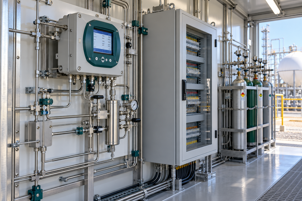
Image: AI-generated editorial illustration, not an exact product photograph or installation reference.
© 2026 NINERMAS. All rights reserved. Official Website: https://ninermas.com Inquiry: sale@ninermas.com | WhatsApp/Tel: +86 18750215667
Next Step
Move the research into a cleaner RFQ.
Send the part number, quantity, condition expectation, destination, and timing details so the sourcing team can reply with better availability and lead-time context.